4.6 Connect Spindles
Hardware Connection · on-board relay, PWM spindle, laser, 0–10 V VFD and RS485 VFD
A VFD runs on mains power and stays dangerous after switch-off. Only the low-voltage signal wires shown here go to the controller, and mains loads belong on the contact side of a relay, in a rated enclosure. Wire and earth the VFD according to its own manual, and test every control signal with the spindle or laser still disconnected.
| Tool | Output | Pin | Speed range | Bench test |
|---|---|---|---|---|
| M6 T0 | On-board relay (on/off spindle) | GPIO.26 | on above S0 | 2.4 |
| M6 T1 | PWM spindle | GPIO.4 | S0–S10000 | 2.5 |
| M6 T2 | Laser | GPIO.12 | S0–S255 | 2.6 |
| M6 T3 | 0–10 V VFD | GPIO.13 + OPT-io.15/OPT-io.14 | S0–S24000 | 2.7 |
| M6 T4 | RS485 Modbus VFD (YL620 profile) | A / B | S0–S24000 | 3.2 |
The 5 V pins are signal outputs, not power outputs. The Outputs (5v) header brings out GPIO.4, GPIO.12, GPIO.14 and GPIO.13 plus GND. They drive the input of a driver, laser module or VFD. GPIO.4 and GPIO.12 are also wired to the two MOSFET channels (1.5 A each, light loads only); anything heavier needs a relay or SSR.
Pick the spindle type that matches your hardware
| What you are connecting | FluidNC section | V4.96 Pro output | Here |
|---|---|---|---|
| Spindle or router that is only on or off | relay | on-board relay, driven by GPIO.26 | E |
| Spindle controller with a PWM / 0–5 V speed input | pwm | GPIO.4 on the Outputs (5v) header | A |
| Laser module with a TTL / PWM input | Laser | GPIO.12 | B |
| VFD with an analog speed input and terminal run commands | 10V | 0–10V terminal — GPIO.13, OPT-io.15, OPT-io.14 | C |
| VFD with an RS485 / Modbus port | YL620 or another named profile | A / B terminals | D |
| Brushless motor through an ESC, or an RC servo | BESC | GPIO.4 / GPIO.12 (raw PWM) | F |
| DC motor through an H-bridge module | HBridge | GPIO.4 + GPIO.12 | G |
| Plasma torch | Plasma | a relay contact + one optocoupler input | H |
| No spindle at all | NoSpindle — created automatically | — | — |
- The section name is the type. Each spindle is a separate block at zero indent in the YAML — there is no
spindles:group around them. Sections A–H below give a working block for each. - G-code has no laser or VFD commands, so FluidNC treats every one of these as a spindle:
M3/M4run it,M5stops it,Ssets the level. M4is only accepted when the section has a direction, forward or reverse pin. Without one, onlyM3andM5mean anything.
💡 FluidNC also has a
DAC spindle type that uses the ESP32's built-in digital-to-analog converter on gpio.25 / gpio.26, at 8-bit resolution into 0–3.3 V. On the V4.96 Pro those two pins already have jobs in the test YAML (the pendant UART and the on-board relay), and the 0–10 V circuit (C) gives a better signal for a VFD anyway.A
PWM spindle — M6 T1
- GPIO.4 → driver PWM / speed input, GND → driver signal ground, both on the Outputs (5v) header.
- 5 kHz PWM. Check with a multimeter first:
S10000≈ 5 V,S5000≈ 2.5 V,M5= 0 V. - GPIO.4 is also wired to one MOSFET channel — using it here means it is no longer free for coolant or a relay.
pwm:
  pwm_hz: 5000
  output_pin: gpio.4
  enable_pin: NO_PIN
  disable_with_s0: false
  s0_with_disable: true
  tool_num: 1
  speed_map: 0=0.000% 10000=100.000%
  off_on_alarm: false
If the board will not start with your laser or drive connected. GPIO.12 and GPIO.15 are two of the pins the ESP32 reads at the instant it powers up, to decide how to start — after that they are ordinary outputs. A device whose input has its own pull-up or pull-down can hold one of them at the wrong level during those first milliseconds. The tell-tale sign: the controller starts fine with the device unplugged, and refuses to start (or refuses a firmware upload) with it connected. Power the controller first, or move that signal to another output pin in your YAML.
B
Laser — M6 T2
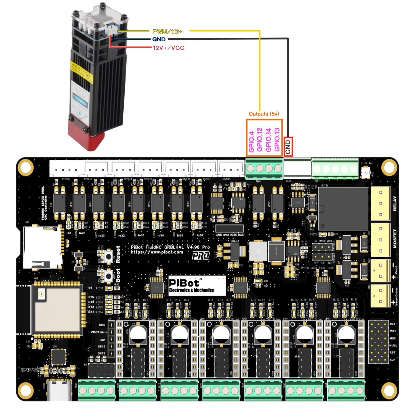
Figure B1 — a laser module has three leads. PWM/TTL+ and GND go to the Outputs (5v) header; 12V+/VCC comes from the module's own supply and never touches the controller — but that supply's negative must sit on the same ground as the controller, or the TTL signal has no return path. The test YAML puts the laser on GPIO.12. Click the image to view it full size.
- GPIO.12 → laser module TTL / PWM input, GND → its signal ground, on the same Outputs (5v) header.
- Scale is 0–255, not 0–10000 — full power is
S255. - The laser only fires while moving. Set power with
M3 S255, then send a move such asG1 F1000. - The on-board relay can switch the laser module's power supply if you want a hard cut-off — see E.
| Mode | Behaviour | Typical use |
|---|---|---|
M3 | Constant power. Stays at the full S value whenever a feed move is active, including a dwell. Turn it off with M5, G0 or S0. | Cutting through material |
M4 | Dynamic power. Scales with feed rate during acceleration and deceleration so corners do not burn darker, and stays off when there is no motion. | Engraving |
- A laser fires only in
G1,G2andG3moves — never duringG0, jogging or homing. If you need output in those modes, use apwmsection instead ofLaser. - Keep
off_on_alarm: trueso a triggered alarm cannot leave the laser burning. - The last entry of
speed_mapis the maximumSyour CAM software should emit —255here.
Laser:
  pwm_hz: 5000
  output_pin: gpio.12
  enable_pin: NO_PIN
  disable_with_s0: false
  s0_with_disable: true
  tool_num: 2
  speed_map: 0=0.000% 255=100.000%
  off_on_alarm: true
C
0–10 V VFD spindle — M6 T3
Check what your drive's
+10V terminal actually is. On the drive in both drawings below it is the reference supply for a manual speed potentiometer, not an input — which is why the figures mark it with a red ×. The V4.96 Pro generates its own 0–10 V, so nothing goes there. Terminal names are not standardised, though — on another brand a terminal printed 10V may be the analog input itself. Identify the analog voltage input in your own manual (it carries a name such as VI, AVI or AI), then take GPIO.13 to it and GND to the analog common (GND / ACM).C1
Five wires, plus the on-board relay as the start / enable contact
Figure C1 — the V4.96 Pro carries its own relay, so the enable contact costs no extra hardware: COMMON goes to the drive's COM and Normal Open to X3. The optocoupler pair still does forward and reverse, and the analog pair still does speed. If your drive needs no enable contact, leave the relay out and set
enable_pin: NO_PIN. Click the image to view it full size.| V4.96 Pro terminal | → VFD terminal | Function |
|---|---|---|
| GPIO.13 (0–10V) | analog voltage input (VI / AVI / AI) | speed reference |
| GND | analog common (GND / ACM) | analog return |
| OPT-io.15 (Out1/Fwd) | forward digital input (X1 / DI1) | run forward |
| OPT-io.14 (Out2/Rev) | reverse digital input (X2 / DI2) | run reverse |
| OPT-Common | digital common (COM / DCM) | shared return for Fwd and Rev |
| on-board relay COMMON / NO | digital common (COM) and X3 (STOP / enable) | the maintained start / enable contact |
OPT-Commonis not a ground. OPT-io.15 withOPT-Common, and OPT-io.14 withOPT-Common, are the two ends of an optocoupler — think of each pair as a switch. Its common end belongs on the drive's digital common (COM / DCM). The separate GND pin on the same terminal block is the return for the 0–10 V signal only, and the two are wired to different places on the drive.- The two channels share one common — they are a pair of switches with a common pole, not two independent floating contacts, so both must return to the same drive terminal.
- The optocoupler output passes no voltage of its own to the drive; it only completes the drive's own input circuit. It does conduct in one direction only — see C2 if your drive uses source-type (PNP) inputs.
- Set the drive to take its run command from the terminals and its speed reference from the analog input, not from the keypad. Parameter numbers differ by brand — look them up in the drive's own manual.
- The 0–10 V output is factory-calibrated to 10 V — only touch the trimmer if your drive needs a different full scale, and watch a multimeter while you do.
- What the G-code does:
M3 S12000closes Fwd and sets the analog voltage;M4releases Fwd and closes Rev;M5releases both contacts and, withs0_with_disable: true, drops the analog output to theS0value at the same time. - The relay contact is a dry contact too, and an independent one — it has its own NC / COMMON / NO terminals and shares nothing with the optocoupler pair.
- Two settings make the relay follow
enable_pin: set the GPIO.26 function-selection jumper to relay output, and give gpio.26 to the10Vsection. It cannot also be therelay:spindle at the same time — see E. - These optocoupler pins are shared with RS485. OPT-io.15 and OPT-io.14 are the same GPIOs the Modbus port uses (D). Use one path or the other, or drive the direction contacts from relays instead (C2).
💡 This page uses the
10V spindle type rather than plain PWM because 10V has separate forward_pin and reverse_pin and releases them on M5. A drive that holds a minimum frequency at 0 V would keep turning if its direction input stayed closed.💡 A concrete example. On a Huanyang drive,
PD001 = 1 takes the run command from the external terminals and PD002 = 1 takes the frequency from the external analog input. Other brands use different numbers for the same two choices — find them in your own manual.10V: forward_pin: gpio.15 # OPT-io.15 Out1/Fwd - X1 (also RS485 TX - pick one) reverse_pin: gpio.14 # OPT-io.14 Out2/Rev - X2 (also RS485 direction - pick one) output_pin: gpio.13 # 0-10V - VI, GND - analog common enable_pin: gpio.26 # on-board relay COMMON-NO across COM and X3 direction_pin: NO_PIN pwm_hz: 5000 disable_with_s0: false s0_with_disable: true spinup_ms: 0 spindown_ms: 0 tool_num: 3 speed_map: 0=0.000% 1000=0.000% 24000=100.000% off_on_alarm: false
C2
Three external contacts — forward, reverse and start/stop- The drive is set for three-wire control, where the STOP input must be held closed before it will start at all.
- A multi-function input is assigned to run-enable or external stop and has to be closed.
- The drive's digital inputs are source (PNP) type. An optocoupler output conducts in one direction only; a relay contact has no polarity and works either way.
- You need contacts with independent commons — the two optocoupler channels share one.
- You want the RS485 port free — relay contacts leave GPIO.15 and GPIO.14 to the Modbus path.
- You want the on-board relay for something else, such as switching the spindle's mains supply.

Figure C2 — three relay contacts do forward, reverse and start/stop, driven from I2SO.23 / I2SO.21 / I2SO.20 plus GND. Those I2SO signals only reach the green terminal when the jumper caps are fitted in that driver slot — a driver module must not be plugged in there. The 0–10 V pair is wired exactly as in C1. Click the image to view it full size.
| Relay | Input | V4.96 signal | → VFD terminal | YAML key |
|---|---|---|---|---|
| K3 | S3 | I2SO.20 | X1 (FWD) | forward_pin |
| K2 | S2 | I2SO.21 | X2 (REV) | reverse_pin |
| K1 | S1 | I2SO.23 | X3 (STOP / enable) | enable_pin |
- The three COM terminals are separate. The board does not join them internally — the drawing bridges them with a short external link so all three contacts return to the drive's COM.
- Each channel is a NC / COM / NO changeover contact. These connections use COM–NO, so a de-energised board leaves the drive stopped.
- The IsoSwitch V4 runs from its own 4.5–40 V DC supply (24 V by default), takes 5 V or 3.3 V logic on S1 / S2 / S3, and its INPUT GND must be tied to the controller GND. Trigger jumpers JP4→S1, JP5→S2, JP6→S3 — full detail in 4.3 Connect External Relay and the IsoSwitch V4 reference.
- Fit the jumper caps, not a driver. The I2SO outputs are routed to the green terminal through that driver slot — as the drawing says, insert the jumper caps and leave the slot free of a driver module.
- In the test YAML I2SO.23 and I2SO.21 are the flood and mist coolant outputs — taking them for the VFD means giving up
M7/M8. Any spare output works; the pin names live in your YAML, not in the hardware. - You can mix the drawings. Keep Fwd and Rev on the optocouplers as in C1 and use the on-board relay for the enable contact — that is exactly what Figure C1 shows.
10V:
  forward_pin: I2SO.20         # K3 - X1 (FWD)
  reverse_pin: I2SO.21         # K2 - X2 (REV)
  enable_pin: I2SO.23          # K1 - X3 (STOP / enable)
  output_pin: gpio.13          # 0-10V - VI, GND - analog common
  direction_pin: NO_PIN
  pwm_hz: 5000
  disable_with_s0: false
  s0_with_disable: true
  spinup_ms: 0
  spindown_ms: 0
  tool_num: 3
  speed_map: 0=0.000% 1000=0.000% 24000=100.000%
  off_on_alarm: false
C3
Two-wire or three-wire — match the drive's own parameter| Terminal control mode set in the drive | What the drive expects | Wiring | YAML |
|---|---|---|---|
| Two-wire — X1 = run forward, X2 = run reverse | a closure held for as long as it should run | Figure C1 | forward_pin + reverse_pin, enable_pin: NO_PIN |
| Two-wire — X1 = run, X2 = direction | one held run contact plus one direction contact | one contact on each input | enable_pin (run) + direction_pin (direction) |
| Three-wire — X1 / X2 = start, X3 = stop | a start command plus a stop input held closed | Figure C2 | enable_pin on the X3 contact — M5 stops the drive by releasing it |
- FluidNC drives levels, never pulses. A contact closes on
M3/M4and opens onM5— which is exactly what two-wire control expects, so start there if your drive offers it. - Three-wire needs the enable contact. Releasing the start input does not stop a latched drive; only opening its STOP input does, and that is the contact
enable_pinholds.
💡 FluidNC writes the direction contacts first and the enable contact last. A three-wire drive that latches on the rising edge of its start input can therefore miss the command. Prove your combination either way: send
M3 S12000 and M5 ten times in a row and confirm every start and every stop. If a three-wire drive is unreliable, switch it to two-wire control.Do not leave a manual pushbutton station wired across the same terminals. A controller contact in parallel with the panel's stop button bypasses that button. And the drive's STOP input is not a safety stop in any wiring: an emergency stop must remove power through a rated safety circuit, not through a terminal command.
D
RS485 Modbus VFD — M6 T4
- A → VFD A, B → VFD B. Two wires only. If it does not communicate, swap A and B — a reversed pair does no damage.
- Internally this is UART1 — TX GPIO.15, RX GPIO.16, direction GPIO.14.
- This is the same pin pair as the 0–10 V Fwd/Rev optocouplers (C): OPT-io.15 and OPT-io.14 are those same GPIOs, so a machine uses either the Modbus path or the optocoupler direction contacts — not both.
- The test YAML ships a
YL620profile as a worked example; match baud, format andmodbus_idto your own drive. - FluidNC carries named profiles for a range of drives — Huanyang, YL620, H100, H2A, the P2 series, NowForever, Danfoss VLT 2800, Siemens V20 — plus the generic
ModbusVFD. Use the section your drive needs; see the Modbus VFD page.
uart1:
  txd_pin: gpio.15
  rxd_pin: gpio.16
  rts_pin: gpio.14
  baud: 9600
  mode: 8N1

YL620:
  uart_num: 1
  modbus_id: 1
  tool_num: 4
  speed_map: 0=0% 0=25% 6000=25% 24000=100%
  off_on_alarm: false
💡 The profile in the test configuration is one worked example. FluidNC also ships named profiles for other drives (Huanyang, H2A, YL620, NowForever…) — see the Modbus VFD page for the section your drive needs.
E
On-board relay — relay · M6 T0
- The V4.96 Pro has a relay on the board — a single NC / COMMON / NO changeover contact driven by GPIO.26. Nothing external is needed for an on/off spindle, a mains contactor coil, a laser power supply or a VFD enable contact.
- Set the GPIO.26 function-selection jumper to relay output first. The same pin can instead be a general-purpose input, and the jumper decides which — see the pinout and jumper pages.
- One job at a time. In the test YAML the relay is its own on/off spindle (
relay:,tool_num: 0, tested withM6 T0thenM3 S255). If you would rather use it as the VFD enable contact of C1, delete thatrelay:section and putenable_pin: gpio.26in the10Vsection instead — FluidNC refuses a configuration that names the same pin twice. - Never drive a relay with a PWM signal — the coil chatters and the contacts fail. The
relayspindle type switches cleanly: anySabove 0 turns it fully on. - For more channels, add a relay module such as the PiBot IsoSwitch V4 and feed it from spare 5 V, I2SO or GPIO outputs — see 4.3 Connect External Relay.
- Mains switching stays on the contact side, in a rated enclosure, with the contact chosen so that a power loss leaves the spindle off. Give
spinup_msa real value — a router needs seconds to reach speed.
relay:
  output_pin: gpio.26          # on-board relay - set the GPIO.26 jumper to relay output
  direction_pin: NO_PIN
  enable_pin: NO_PIN
  disable_with_s0: false
  s0_with_disable: true
  spinup_ms: 3000              # let the spindle reach speed before cutting
  spindown_ms: 3000
  tool_num: 0
  off_on_alarm: true
F
Brushless ESC or RC servo — BESC
- For a brushless motor driven through an ESC (the drone/RC kind, used as a light high-speed spindle), or for a hobby servo such as a pen lift.
- The signal is RC-style: a pulse of roughly 1–2 ms inside a 20 ms period, so
pwm_hz: 50.min_pulse_usandmax_pulse_uscome from your ESC's own documentation, andspeed_mapis then a plain percentage of that span — no duty-cycle arithmetic. - It needs a raw PWM pin: GPIO.4 or GPIO.12 on the Outputs (5v) header. Do not use the 0–10 V terminal — that output is a filtered analog voltage, not a pulse train.
- Three wires: signal, ground and power. The signal goes to GPIO.4 or GPIO.12, the ground to that header's GND, and the power to a 5 V source on the board for a small servo, or its own supply for an ESC and motor.
- An ESC that expects an arming sequence at power-up can be walked through it from G-code —
M3 S0for minimum throttle,M3 S1000for full,M3 S500for mid. - The same section drives a pen-lift servo:
M3 S1000down,M5up. FluidNC also has an RC servo axis feature if you want it on an axis instead.

Figure F1 — the wiring path for a 5 V hobby servo: signal (white) to a PWM pin on the Outputs (5v) header, black to that header's GND, and red to a +5V pin on the board. The servo in the photograph is there to show the three leads, not as a recommended size — see the note below. Click the image to view it full size.
Watch the servo's current. A servo draws far more while it moves — and more again if it stalls — than while it sits still. That +5V is the board's own regulated rail, produced by the on-board step-down converter from the main power input — so it shares its budget with the rest of the board. Treat it as a supply for a light servo — a pen lift, a tool-cover flap. Anything with real torque, including the class of servo in the photograph, and any ESC-driven motor, needs its own 5 V supply, with only the ground shared with the controller.
BESC:
  output_pin: gpio.4           # raw PWM pin - not the 0-10V terminal
  pwm_hz: 50                   # 20 ms period
  min_pulse_us: 1000           # ESC "off" pulse - check its datasheet
  max_pulse_us: 2000           # ESC full-power pulse
  tool_num: 5
  speed_map: 0=0% 1000=100%
G
DC motor through an H-bridge — HBridge
- Like a PWM spindle, but with one PWM output per direction. While one is toggling the other is held low, and
M5turns both off. - GPIO.4 and GPIO.12 are the two PWM-capable 5 V outputs — the natural pair for
output_cw_pinandoutput_ccw_pin. They drive the inputs of an H-bridge module, which needs its own supply. - Neither the MOSFET channels nor the on-board relay can do this. The MOSFETs are low-side switches and the relay is a single changeover contact — they can turn a DC load on and off, but they cannot reverse it.
- There is no
direction_pinin this section — the two output pins carry the direction.
HBridge:
  pwm_hz: 5000
  output_cw_pin: gpio.4
  output_ccw_pin: gpio.12
  enable_pin: NO_PIN
  disable_with_s0: false
  spinup_ms: 1000
  spindown_ms: 1000
  tool_num: 6
  speed_map: 0=0.000% 10000=100.000%
  off_on_alarm: false
H
Plasma torch — Plasma
- This section has no speed output.
enable_pinfires the torch, andarc_ok_pinis an input that confirms the arc transferred. - If
arc_ok_pingoes inactive while cutting, motion is aborted with an alarm.arc_wait_msis how long FluidNC waits for the confirmation before giving up. - On the V4.96 Pro: fire the torch through the on-board relay or an external contact (E), and take arc OK into one of the optocoupler-isolated inputs you are not using for limits. Add
:lowif the signal is active-low. - Plasma is a development feature in FluidNC — read its own plasma page for the hardware notes before wiring a torch.
Plasma:
  enable_pin: gpio.26          # torch start through the on-board relay
  arc_ok_pin: gpio.39:low      # an optocoupler input you are not using for limits
  arc_wait_ms: 1000
  tool_num: 7
  off_on_alarm: true
I
Settings every spindle section shares
| Setting | What it does | Notes |
|---|---|---|
tool_num | Where this spindle's tool range starts | The range runs until the next spindle's tool_num. One spindle must have tool_num: 0 so every tool number is valid. |
speed_map | Maps the S value to the output | 0=0.000% 1000=0.000% 24000=100.000% means S below 1000 gives nothing — a minimum-speed floor. Full syntax on FluidNC's speed map page. |
enable_pin | A separate line held on while the spindle runs | The start / enable contact in C2. Affected by disable_with_s0. |
direction_pin | Reverse signal | M4 is only accepted when this — or forward_pin/reverse_pin in a 10V section — is assigned. |
spinup_ms / spindown_ms | Wait after a speed change before the next move runs | 0–60000 ms, scaled to the size of the change: half the range costs half the time. |
disable_with_s0 | Also disable at S0, not only at M5 | Default false. |
s0_with_disable | Drive the speed output to its S0 value on M5 | Leave true so the analog or PWM output actually falls to zero when you stop. |
off_on_alarm | Turn the spindle off when an alarm occurs | Recommended true for a laser, and worth it for a torch. |
atc / m6_macro | Automatic tool change, or a macro to run instead of the built-in M6 | Optional — see the FluidNC spindle configuration page. |
J
Using more than one spindle
- Define as many as your hardware supports. Each is its own section and they act independently — a machine can carry a router, a laser and a VFD at once.
- Every spindle needs its own pins. The config parser rejects a pin used twice, and FluidNC has to be able to control each spindle separately during tool changes and alarms.
- Tool numbers decide which spindle is active.
tool_numis the first tool of that spindle's range, and the range runs until the next spindle'stool_num. One of them must be0so every tool number is valid — and that is the spindle you get at power-on, before anyM6. - Keep
TandM6on the same line, the way the bench pages writeM6 T2. ATon its own only sets the next tool; the change happens onM6. Send$Gto read back the current tool and modal state. - Send
M5before switching, so the previous output is left at zero. - Use shielded cable for the analog and RS485 runs, and keep them away from motor and limit-switch wiring. A VFD is the noisiest device on the machine.
!
One pin, one job — what shares what on this board| Signal | Its job in the test YAML | If you want it for a spindle instead |
|---|---|---|
| GPIO.26 | The on-board relay as an on/off spindle (relay:, T0), only when its function jumper selects relay output | Give it to the 10V section as enable_pin instead (C1) — one or the other |
| GPIO.15 / GPIO.14 | RS485 TX and direction (uart1, YL620 profile) | The same pins are the OPT-io.15 / OPT-io.14 Fwd/Rev optocouplers — use the Modbus path or the direction contacts, not both |
| GPIO.4 / GPIO.12 | PWM spindle (T1) and laser (T2); the same two pins drive the MOSFET channels | One job each — a BESC or HBridge output takes the place of that spindle |
| I2SO.23 / I2SO.21 / I2SO.20 | Flood and mist coolant (M7/M8); reach the green terminal only with the jumper caps fitted in that driver slot | Give them up and they drive the three relay inputs in C2 |
💡 The five paths in the test YAML (
M6 T0 relay, T1 PWM, T2 laser, T3 0–10 V, T4 RS485) already follow these rules. Sections F–H above use tool numbers 5–7 so you can add one without disturbing them — but check the table above first: on this board several pins wear two hats.K
Also possible: an RC servo or solenoid as an axis
- A spindle is not the only way to drive an RC servo or a solenoid. FluidNC can also make one an axis, so
G0 Z5moves it — useful for a pen lift or a tool cover.
z:
  steps_per_mm: 100.000
  max_rate_mm_per_min: 5000.000
  acceleration_mm_per_sec2: 100.000
  max_travel_mm: 5.000
  soft_limits: true
  homing:
    cycle: 1
    positive_direction: true
    mpos_mm: 5.000

  motor0:
    rc_servo:
      pwm_hz: 50
      output_pin: gpio.27
      min_pulse_us: 1000
      max_pulse_us: 2000
- To reverse the travel, swap the two pulse widths:
rc_servo:
  pwm_hz: 60
  output_pin: gpio.27
  min_pulse_us: 2000
  max_pulse_us: 1000
Quick troubleshooting
- Laser voltage is right but it never fires. Expected — send a
G1 F1000move after setting the power. - Laser always at full power. Its scale is 0–255; an
S10000clamps to maximum. - VFD ignores the speed signal. It is still set to keypad reference — change its source parameters.
- RS485 silent. Swap A and B, then check baud, format and
modbus_id. - Direction inverted. Swap the wires on the drive's forward and reverse inputs.
- The spindle keeps turning after
M5. A three-wire drive stays latched until its STOP input opens — wire that contact as in C2 and assign it toenable_pin. - The drive runs from its own panel but not from
M3. Its digital inputs may be source (PNP) type — the optocoupler outputs conduct in one direction only. Use a relay contact (C2) instead, and check that the optocoupler common went to the digital common (COM / DCM), not to the analog GND. - Nothing on any output. Select the tool first with M6.
- A spindle you just added does nothing. Check the tool numbers: one section must have
tool_num: 0, the ranges must not overlap, andM6has to select this one. - An ESC beeps and never spins. It has not been armed — walk it through its throttle sequence with
M3 S0/M3 S1000, and checkmin_pulse_us/max_pulse_usagainst its datasheet. - A relay chatters or dies. It is being fed a PWM signal — use a
Relaysection, notpwm.