pibot_cnc_laser_series:v588_ultra:test_laser:start
2.10 Test Laser Output
Check List · Step 10 of 12 · Measure the GPIO.46 laser output at 0% / 50% / 100%
🎯 Objective
Test the laser output on GPIO.46 (the PWM 5V header, next to the PWM pin). You'll set it to a few levels and confirm the voltage and the indicator LED follow along. A multimeter is all you need — no oscilloscope required.
🔌 How it works: the laser output is the same kind of 5 kHz PWM as step 2.9 — the duty cycle sets the average voltage the meter reads. Two things to get right: this output is scaled 0–255, so full power is S255 (not S10000); and on this firmware the laser only fires while moving — so after you set the power with
M3 S, you send a separate G1 F1000 move (a second Enter), and the laser fires on that move. Select tool T1, not T0.
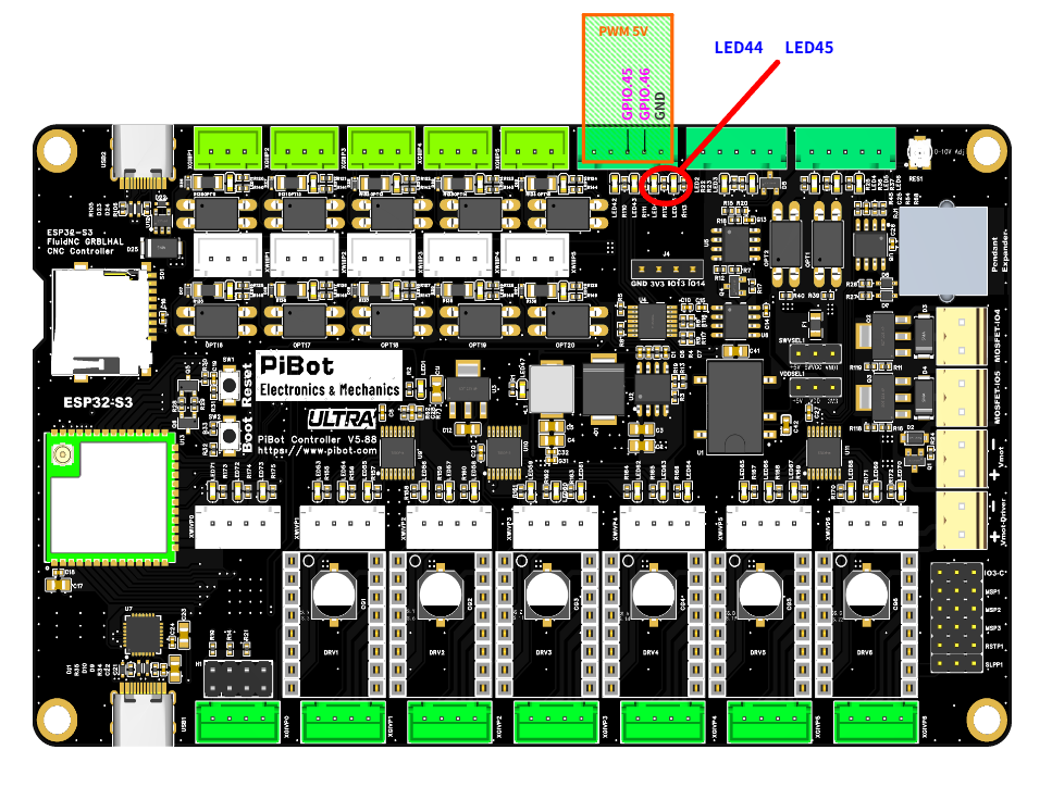
The PWM 5V header — GPIO.45 (PWM), GPIO.46 (Laser), GND — and the output LEDs (red circle): GPIO.45 → LED44, GPIO.46 → LED45. (click to enlarge)
🔧 How to Measure
Set the multimeter to DC voltage, auto-range. On the PWM 5V header:
RED (+) → GPIO.46
BLACK (−) → GND
Red on GPIO.46, black on GND. Full power (
S255) reads ≈ 5 V.Type each command into the WebUI command line and press Enter — one line at a time. The laser stays dark until the G1 F1000 move runs:
M6 T1
→
Select the laser (tool 1)
M3 S255
→
Set full power — nothing fires yet
G1 F1000
→
5.0 Vnow it fires — LED45 full bright
M3 S128
→
Set half power
G1 F1000
→
2.5 VLED45 half bright
M5
→
0.0 VLED45 off
✅ Pass: the reading tracks the value — about 5 V at full power, 2.5 V at half, 0 V after
M5 (each power set, then a G1 F1000 move) — and LED45 (the GPIO.46 indicator) brightens and dims to match. If it does, the laser output is good.📈 Optional — what GPIO.46 looks like on an oscilloscope (you don't need one; this is just to show what PWM is):
pibot_cnc_laser_series/v588_ultra/test_laser/start.txt · Last modified: by admin