
pibot_cnc_laser_series:v588_ultra:test_extra_io:start
2.7 Test Extra I/O
Check List · Step 7 of 12 · Toggle the two Extra I/O user outputs with M64 / M65
🎯 Objective
This step checks GPIO.10 and GPIO.15 on the Extra I/O header. The test YAML maps them to FluidNC user outputs P0 and P1; you will switch each one on and off with M64 / M65 and watch its indicator LED. No wiring and no multimeter needed. GPIO.3 stays in input mode as the toolsetter and was already tested in section 2.5.
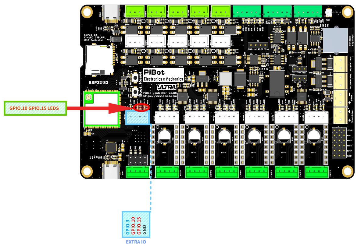
The two spare-output LEDs (red circle) and the EXTRA IO header — GPIO.3 / GPIO.10 / GPIO.15 / GND. (click to enlarge)
🧪 How to Test
Open the FluidNC WebUI and type each command below into the command line. Watch the two LEDs circled in red on the photo.
M64 P0
→
The GPIO.10 LED turns ON (user output P0)
M65 P0
→
The GPIO.10 LED turns OFF
M64 P1
→
The GPIO.15 LED turns ON (user output P1)
M65 P1
→
The GPIO.15 LED turns OFF
✅ Pass: GPIO.10 follows
M64 P0 / M65 P0, and GPIO.15 follows M64 P1 / M65 P1.💡 6+1 capability: the Extra I/O header is GPIO.3 / GPIO.10 / GPIO.15 / GND. In this test YAML, GPIO.3 is the toolsetter input while GPIO.10 and GPIO.15 are ordinary outputs. For a machine-specific seventh axis, GPIO.3 must be switched to output mode and all three signals reassigned as Step / Dir / Enable; they cannot keep their test-YAML I/O roles at the same time.
pibot_cnc_laser_series/v588_ultra/test_extra_io/start.txt · Last modified: by 127.0.0.1