pibot_cnc_laser_series:v588_ultra:test_endstops:start
2.5 Test Probe and Endstop Inputs
Check List · Step 5 of 12 · Use jumper caps to test the probe and limit switch input signals
ℹ️
Objective: This step checks whether the probe and limit switch input circuits are working correctly. Each input is tested by shorting its SIGNAL pin to GND with a jumper cap.
⚠️
SAFETY FIRST: Please ensure correct pin connections to avoid short circuits during testing. Only short the specified SIGNAL and GND pins.
1
Initial Limits Check
- Make sure there is no short circuit between any input signal pin and GND before testing.
- Open the WebUI command line.
- Enter command: $limits
- Before inserting jumper caps, the monitor should scroll without trigger indications.
Display before inserting jumper caps:
$limits
Send ! to exit
Homing Axes : xyzabc
Limit Axes :
  PosLimitPins NegLimitPins Probe Toolsetter
:
:
:
:
:
:
:
2
Trigger Test with Jumper Caps
💡 Use jumper caps to short each input SIGNAL pin to GND. There are 10 inputs to test in total. Test them one by one, or install all 10 jumper caps for a full trigger check.
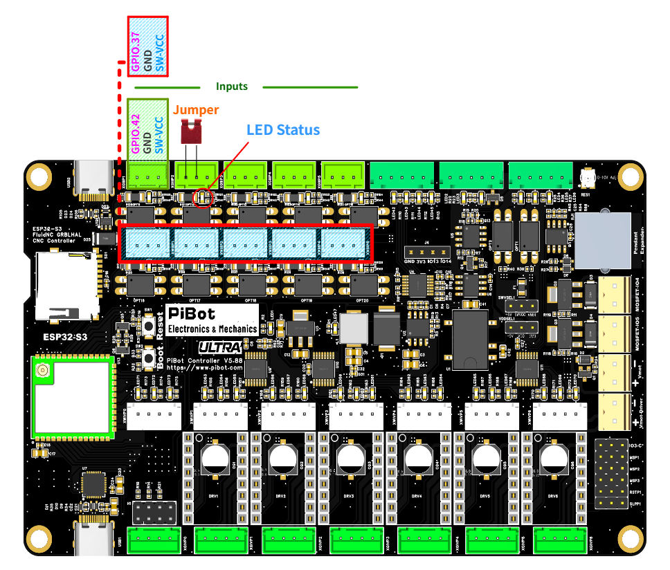
Reference image: insert jumper caps between SIGNAL and GND for the probe and endstop input test.
- ⚠️ DO NOT short incorrect pins.
- Insert jumper caps between SIGNAL and GND.
- There are 10 jumper positions to test.
- After inserting the jumper caps, all tested switches and endstops should show a triggered state.
- The corresponding motherboard input indicator LEDs should all illuminate.
Display after inserting jumper caps:
:  xy                      xyzabc                  P T
:  xy                      xyzabc                  P T
:  xy                      xyzabc                  P T
:  xy                      xyzabc                  P T
:  xy                      xyzabc                  P T
At the same time, the corresponding input indicator LEDs on the motherboard should be ON.
3
Exit Monitor Mode
- After checking the triggered state, enter: !
- The exclamation mark command exits the $limits monitoring mode.
- Make sure the command line returns to normal operation before continuing.
4
Jumper Removal
- Remove all jumper caps used for shorting SIGNAL and GND.
- After removal, the system should return to the normal un-triggered state.
- The corresponding motherboard input LEDs should turn off.
🔧 Quick Troubleshooting
- If an input is already triggered before inserting a jumper cap, check whether SIGNAL and GND are shorted.
- If an input does not trigger after inserting a jumper cap, check whether the jumper is inserted on the correct SIGNAL and GND pins.
- If the LED does not light, re-check the jumper position and make sure the board is powered on.
- If the command keeps scrolling and you want to stop monitoring, enter !.
✓
Expected Results
- The initial $limits command shows scrolling status without any trigger indication.
- When SIGNAL and GND are shorted with jumper caps, all tested probe and endstop inputs show a triggered state.
- When all 10 jumpers are inserted correctly, the corresponding input indicator LEDs illuminate.
- After entering !, the system exits limit monitor mode.
- After removing the jumper caps, the system returns to the normal un-triggered state.
pibot_cnc_laser_series/v588_ultra/test_endstops/start.txt · Last modified: by admin