pibot_cnc_laser_series:v588_ultra:test_0_10v:start
2.11 Test 0-10V Output
Check List · Step 11 of 12 · Measure the GPIO.6 analog output for a VFD spindle
🎯 Objective
Test the 0–10 V analog output on GPIO.6 — the speed signal a VFD spindle uses. You'll set a few speeds, check the voltage on a multimeter, and try forward and reverse. It's already calibrated to 10 V at the factory, so this is mostly a check.
🔌 How it works: unlike the PWM pins, this is a true analog voltage from 0 to 10 V that tells a VFD how fast to spin —
S24000 = 10 V (full), S12500 = 5 V, M5 = 0 V. Direction is separate: M3 = forward (lights LED5), M4 = reverse (lights LED4); the 0–10 V level is the same either way. LED6 lights whenever there's output (brighter at higher voltage), so it's on for both directions.
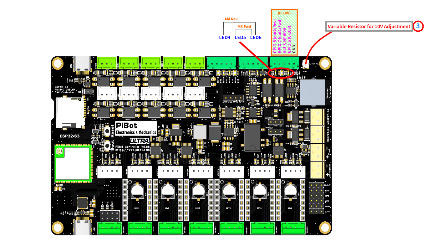
The 0–10V terminal — GPIO.8 (Rev), GPIO.7 (Fwd), out Common, GPIO.6 (0–10V), GND — the indicators (LED4 Rev, LED5 Fwd, LED6 0–10V), and the 10V adjustment trimmer (item 3). (click to enlarge)
🔧 How to Measure
Set the multimeter to DC voltage, auto-range. On the 0–10V terminal:
RED (+) → GPIO.6 (0–10V)
BLACK (−) → GND
Red on GPIO.6, black on GND. Full speed (
S24000) reads ≈ 10 V.Send M6 T2 first to select the 0–10V output, then send each command (press Enter after each):
M6 T2
→
Select the 0–10V output (tool 2)
M3 S24000
→
10.0 Vforward — LED5 + LED6 on
M3 S12500
→
5.0 Vhalf speed — LED5 on, LED6 dimmer
M4 S24000
→
10.0 Vreverse — LED4 + LED6 on
M5
→
0.0 Voff — all LEDs off
🧮 Why S12500 for half — not S12000?
The 0–10V speed map has a small dead-band at the very bottom:
speed_map: 0=0.000% 1000=0.000% 24000=100.000%
So S0–S1000 all give 0 V, and the voltage then rises straight-line from S1000 (0 V) up to S24000 (10 V). The output is:
output% = (S − 1000) ÷ (24000 − 1000) × 100%
For half (5 V): S = 1000 + 0.5 × 23000 = 12500. That's why half voltage is S12500, not S12000 — S12000 would actually give about 4.8 V.
🔧 Calibrating the 10 V (usually not needed)
🏭 We already set this output to exactly 10.0 V at the factory, using a 24 V supply — so under 24 V power it should already read 10 V at
If you do want to fine-tune: send
S24000, and you normally don't need to touch it.If you do want to fine-tune: send
M6 T2 then M3 S24000, and slowly turn the 10V adjustment trimmer (item 3 in the photo) while watching the meter until it reads 10.0 V.
⚠ Use a small screwdriver only. The trimmer is a tiny SMD pot with a 1.5 ± 0.05 mm slot. Use a 1.5 mm flat-head micro screwdriver (best fit) or a 1.2 mm one. Never use a large screwdriver — the extra leverage puts too much torque on the pot and will break it in one turn.
✅ Pass: the meter reads about 10 V at
S24000 and 5 V at S12500; M3 lights LED5 (Fwd) and M4 lights LED4 (Rev); M5 returns to 0 V. If so, the 0–10V output is good.pibot_cnc_laser_series/v588_ultra/test_0_10v/start.txt · Last modified: by admin