
pibot_cnc_laser_series:v577_carrier:test_mosfet:start
2.8 Test MOSFET Output
Check List · Step 8 of 12 · Test GPIO.4 and GPIO.5 MOSFET outputs with M7 / M8 / M9
🎯 Objective
The board has two MOSFET outputs, io.4-MOS-GND and io.5-MOS-GND. The V5.77 test YAML assigns GPIO.4 to mist coolant (M7) and GPIO.5 to flood coolant (M8); M9 turns both off. Confirm each channel across its two-pin terminal with a multimeter.
🔌 How it works: each output is a low-side MOSFET. The pin name
io.4-MOS-GND tells you it is the GND side that output io.4 switches. In normal use your load wires between Vmot-Main (+) and io.X-MOS-GND; turning the output ON connects io.X-MOS-GND to GND, so the full motor voltage (Vmot, ~24 V) appears across the load. With no load attached, the multimeter reads that voltage straight across the two terminal pins — about 0 V when off, ~24 V when on. Maximum current is 1.5 A per channel. For heavier loads, use an external relay or suitable power driver; overloading can burn the MOSFET.
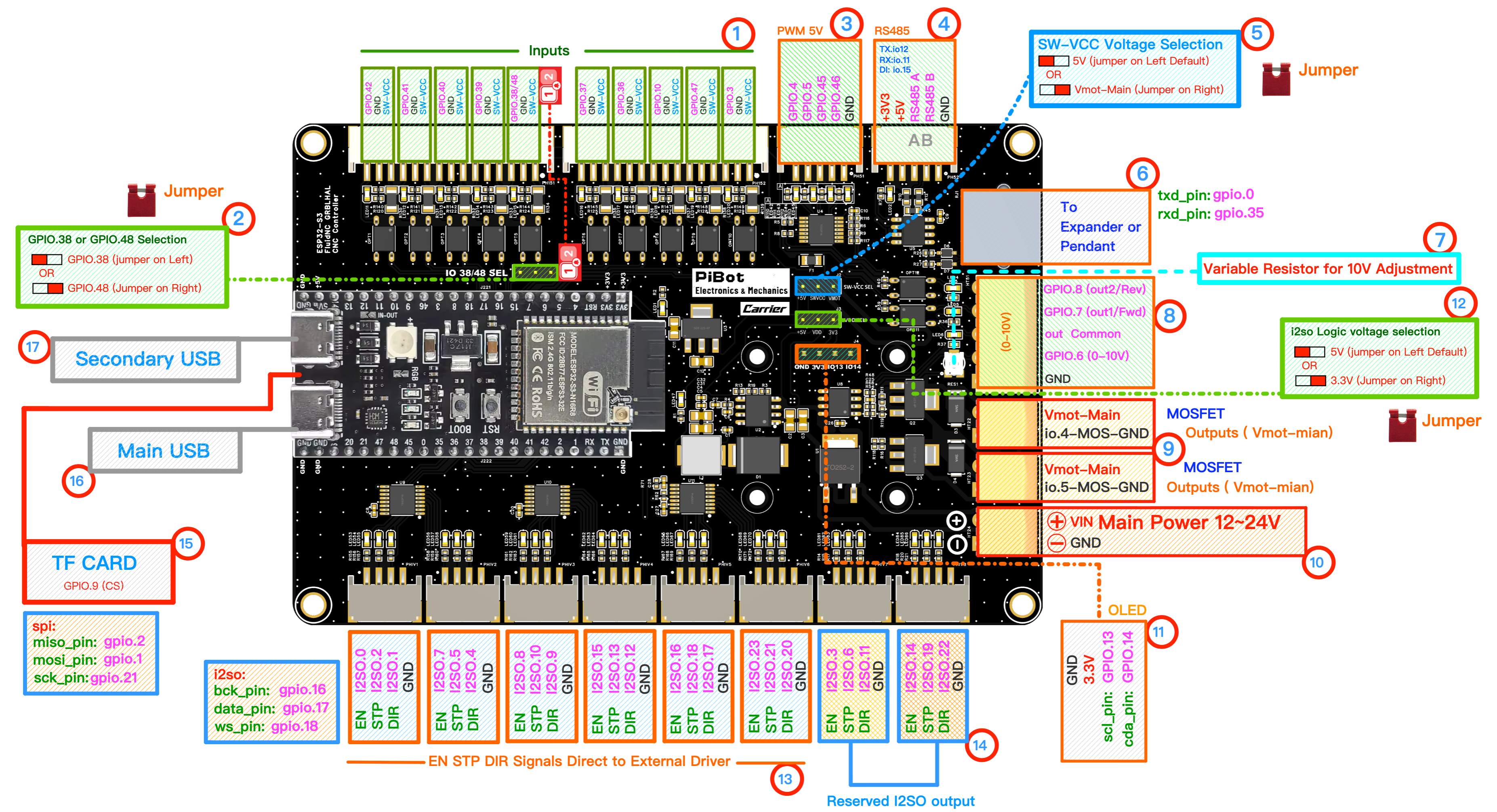
The two MOSFET terminals (right, orange) — each has an io.X-MOS-GND pin (top) and a Vmot-Main pin (bottom) — and their indicator LEDs (red circle, GPIO.4 / GPIO.5). (click to enlarge)
🔧 How to Measure
Set the multimeter to DC voltage, auto-range. On the orange io.4-MOS-GND terminal, put the probes across its two pins — top pin and bottom pin, exactly as in the photo:
RED (+) → Vmot-Main (bottom)
BLACK (−) → io.4-MOS-GND (top)
With nothing switched on it reads about 0 V. (If the meter shows a minus sign, your probes are reversed — just swap them.)
GPIO.4 —
io.4-MOS-GND terminal
M7
→
24.0 VGPIO.4 LED on
M9
→
0.0 VLED off
👈 Now move both probes to the io.5-MOS-GND terminal — same way: RED (+) on Vmot-Main (bottom), BLACK (−) on io.5-MOS-GND (top).
GPIO.5 —
io.5-MOS-GND terminal
M8
→
24.0 VGPIO.5 LED on
M9
→
0.0 VLED off
✅ Pass: each terminal reads approximately the VIN Main supply voltage when its command is on and returns to about 0 V after
M9. The GPIO.4 / GPIO.5 indicator LED should follow the command.⚠ Careful: Vmot-Main carries the full 12-24 V supply. Do not let the probe tips touch each other. Use an external relay or power driver for larger loads, and verify load polarity before connection.
pibot_cnc_laser_series/v577_carrier/test_mosfet/start.txt · Last modified: by 127.0.0.1