
pibot_cnc_laser_series:v577_carrier:check_jumpers:start
2.2 Check Jumpers and Power On
Check List · Step 2 of 12 · Check the default jumpers, seat the module, then power on safely
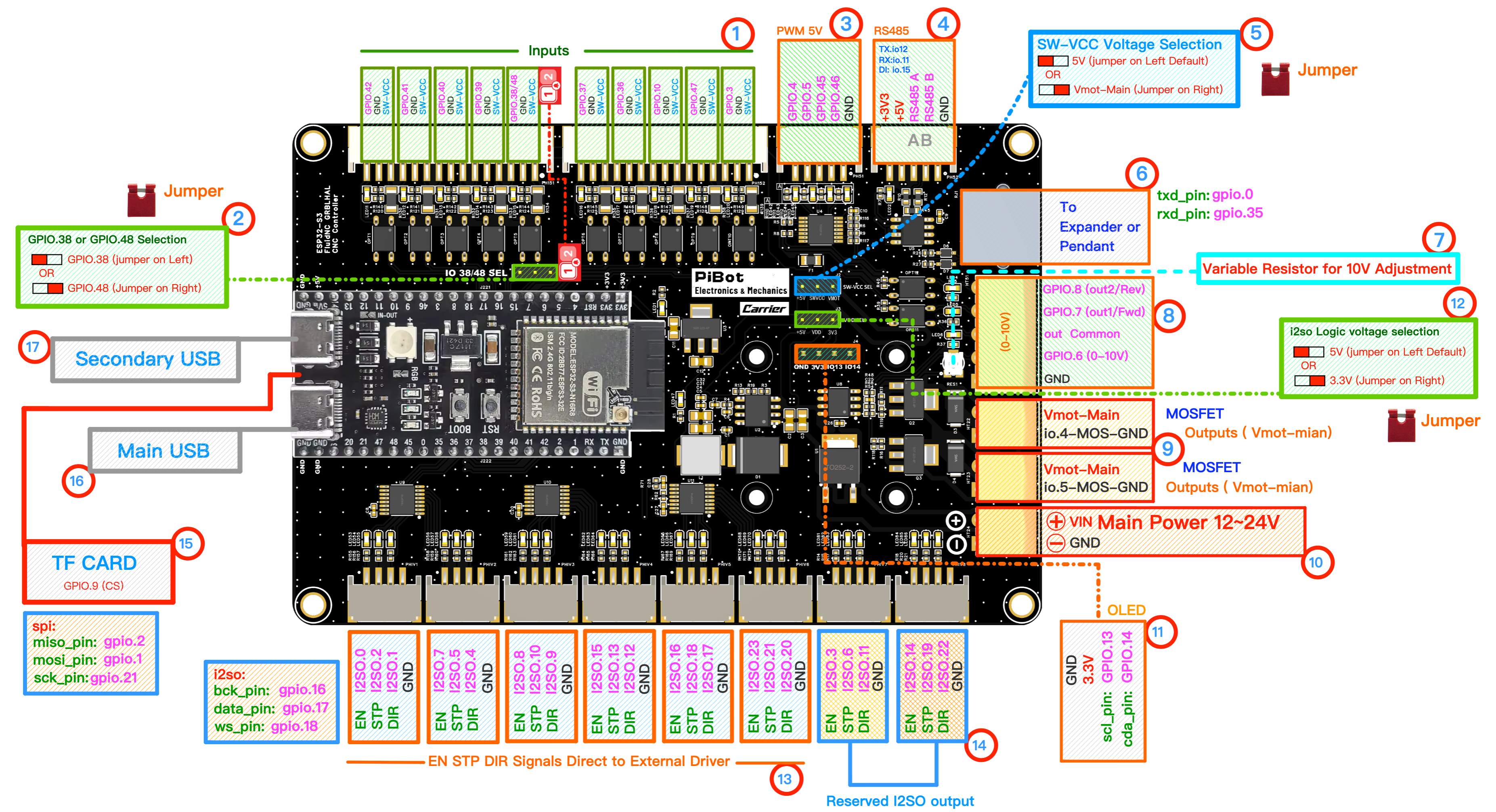
Use the circled numbers in this diagram to find each jumper, connector, and module position.
⚠️
SAFETY FIRST: Please disconnect all external peripherals before starting the inspection process.
🎯 Objective
Before the first power-on, confirm that the ESP32-S3 module is seated and the factory default jumpers are installed in the correct positions. Then connect the main power input and check the basic power-on result.
1
Module and Jumpers
💡 Only 3 jumper caps are installed by default from the factory.
- ESP32-S3 module: confirm the plug-in module is fully seated in its socket, in the orientation shown by the silkscreen.
- 5SW-VCC Voltage Selection: select 5V.
- 2GPIO.38 / GPIO.48 Selection: select GPIO.38 (jumper on left) to match the default YAML.
- 12I2SO Logic Voltage Selection: select 5V.
2
Module Insert
- Insert the Antenna (if your ESP32-S3 module has an IPEX connector).
- 11Insert the OLED (optional).
- 15Insert the TF Card / microSD Card (optional).
3
Power On
- 10Connect 12V or 24V power to VIN Main Power.
- ⚠️ Do not reverse polarity.
- Default: 24V recommended.
- Switch on power.
✓
Expected Results
- The power indicator LED should illuminate.
- 11The OLED screen should display information/data (if firmware installed).
⚠️
If the power LED does not turn on, switch off power immediately and re-check the input voltage, polarity, module seating, and jumper positions before continuing.
pibot_cnc_laser_series/v577_carrier/check_jumpers/start.txt · Last modified: by 127.0.0.1