
pibot_cnc_laser_series:v47b:test_mosfet:start
2.8 Test MOSFET Outputs
Check List · Step 8 of 12 · Measure the GPIO.4 and GPIO.12 low-side channels
🎯 Objective
Confirm both orange MOSFET terminals switch correctly with a multimeter. Test io.4-MOS-GND first, then io.12-MOS-GND. Keep all loads disconnected.
1.5 A maximum per channel; light loads only. Heavy loads require an external relay or suitable power driver. Overloading can burn the MOSFET. Never short Vmot-main directly to MOS-GND.
🔌 How it works: these are low-side switches. The load would sit between Vmot-main (+) and io.X-MOS-GND. When the MOSFET turns on, it connects the MOS-GND side to ground, so the meter across the two terminal pins reads approximately the main supply voltage.
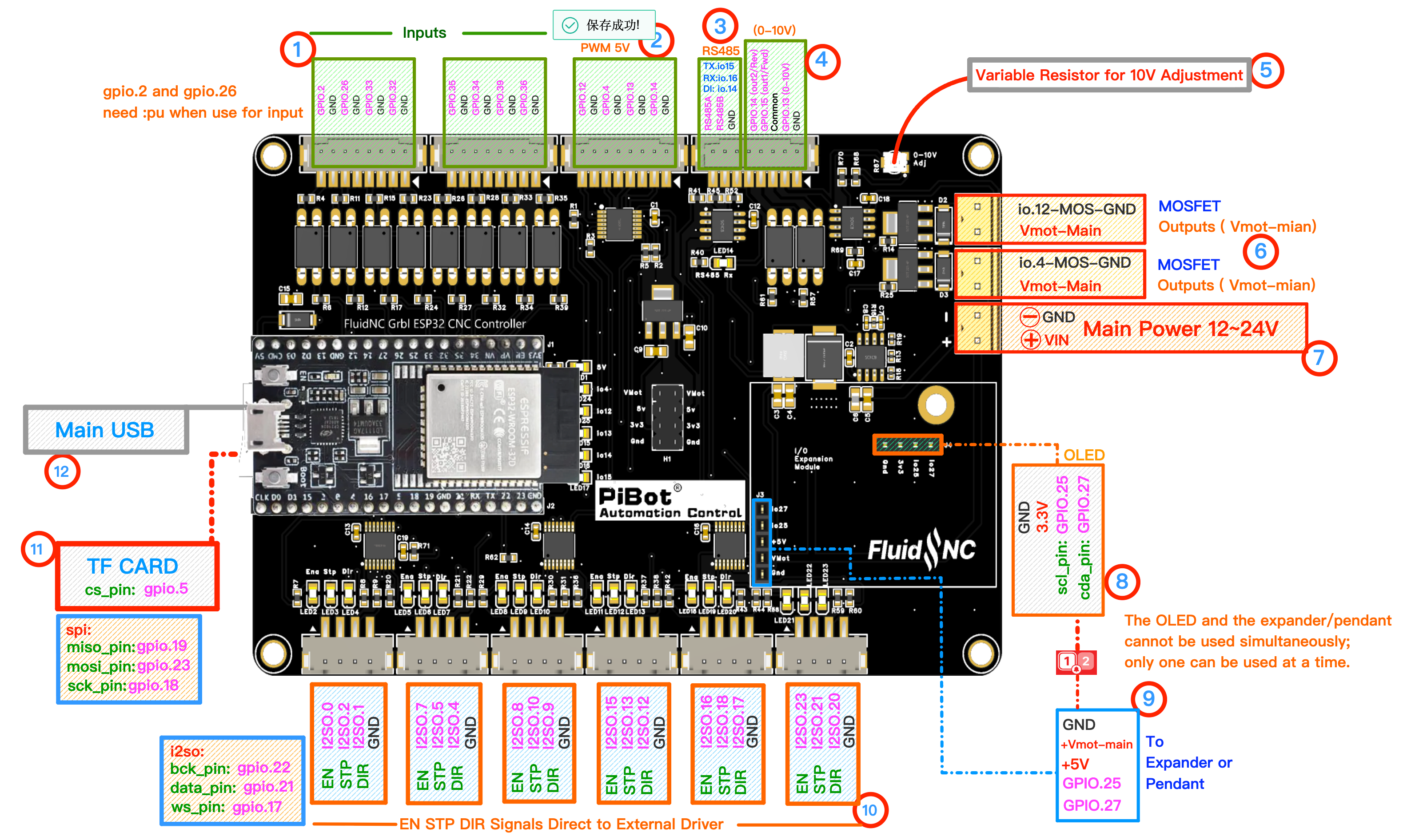
Use numbered area ⑥ MOSFET Outputs. Each orange two-pin terminal has one Vmot-main pin and one switched MOS-GND pin. Click to enlarge.
🔧 How to Measure
Set the multimeter to DC voltage, auto-range. Test one orange terminal at a time.
RED (+) → Vmot-mainBLACK (−) → io.4-MOS-GND or io.12-MOS-GND
Red on Vmot-main, black on the selected io.X-MOS-GND. With a 24 V supply, ON reads about 24 V and OFF about 0 V.
1 — Test io.4-MOS-GND
M6 T0→Select GPIO.4 / tool 0
M3 S10000→about VmotGPIO.4 channel on
M5→about 0 Vchannel off
2 — Test io.12-MOS-GND
M6 T1
G91→Select GPIO.12 laser output; relative motion
G91→Select GPIO.12 laser output; relative motion
M3 S255
G1 X1 F100→about Vmotduring the short move
G1 X1 F100→about Vmotduring the short move
M5
G90→about 0 Vchannel off; restore absolute motion
G90→about 0 Vchannel off; restore absolute motion
✅ Pass: each channel changes from about 0 V to approximately Vmot-main when commanded, returns to about 0 V after
M5, and the other channel remains off.pibot_cnc_laser_series/v47b/test_mosfet/start.txt · Last modified: by 127.0.0.1