
pibot_cnc_laser_series:v47b:test_laser:start
2.10 Test Laser Output
Check List · Step 10 of 12 · Measure GPIO.12 laser PWM at 0% / 50% / 100%
🎯 Objective
Test the GPIO.12 laser PWM output using a multimeter while the actual laser remains disconnected. The output is motion-controlled, so each power command is followed by a short safe relative move.
The laser module must be physically disconnected. This page tests only the controller signal. Motors and external drivers should also remain disconnected while using the relative-motion commands below.
🔌 How it works: the test YAML maps laser power 0–255 to a 5 kHz PWM signal. The multimeter reads the average voltage:
S255 is about 5 V, S127 about 2.5 V, and M5 0 V.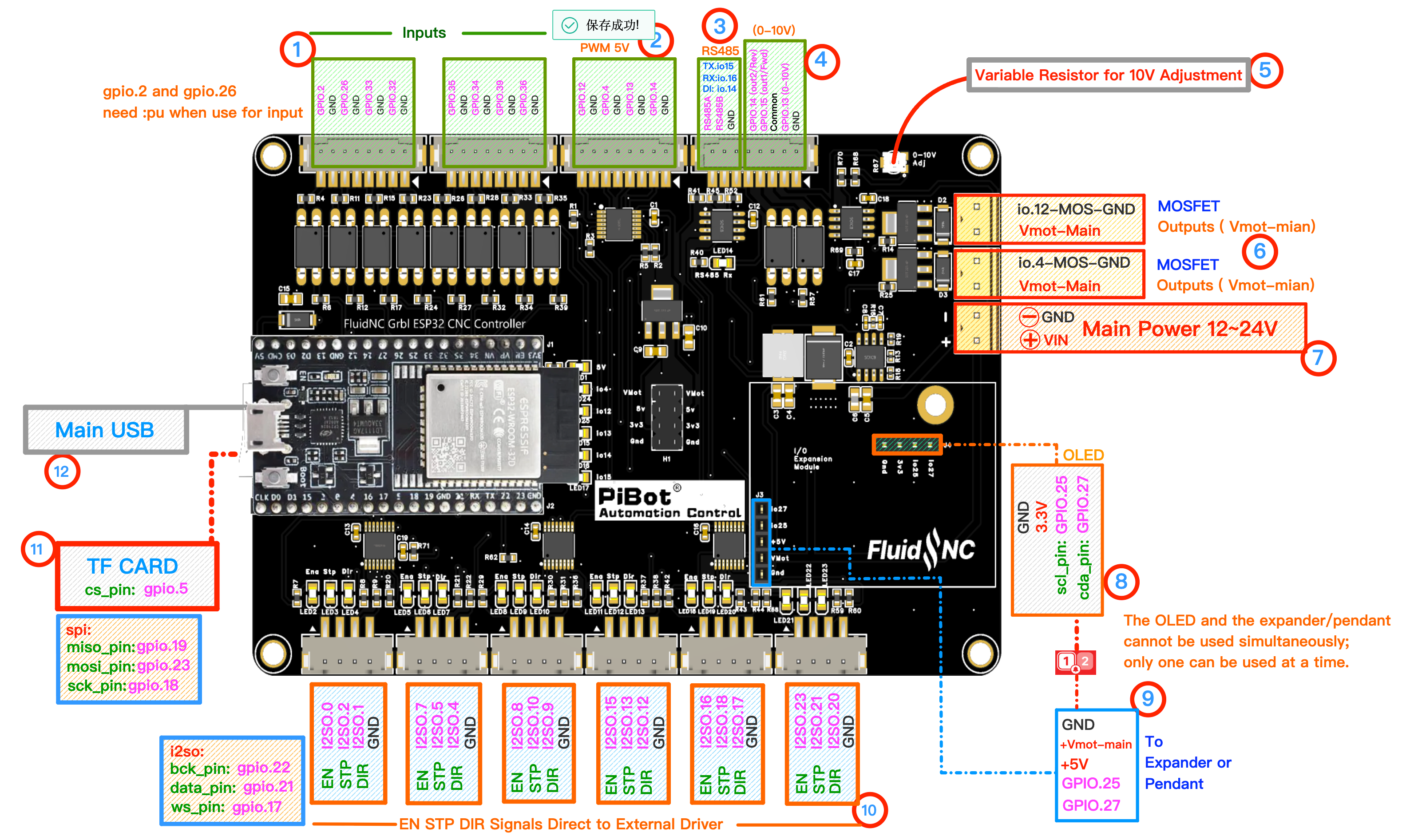
Use numbered area ② PWM 5V. The GPIO.12/GND pair is the first pair in that header. Click to enlarge.
🔧 How to Measure
Set the multimeter to DC voltage, auto-range.
RED (+) → GPIO.12BLACK (−) → adjacent GND
Red on GPIO.12, black on its adjacent GND. At half power the average is about 2.5 V.
Send the following commands one row at a time. Wait for the short move and watch the meter.
M6 T1→Select laser output (tool 1)
G91→Use relative motion for the short signal test
M3 S255
G1 X1 F100→about 5.0 Vduring motion
G1 X1 F100→about 5.0 Vduring motion
M3 S127
G1 X-1 F100→about 2.5 Vduring motion
G1 X-1 F100→about 2.5 Vduring motion
M5
G90→0.0 Voutput off; restore absolute motion
G90→0.0 Voutput off; restore absolute motion
✅ Pass: GPIO.12 reaches about 5 V at
S255, about 2.5 V at S127 during motion, and returns to 0 V after M5.📈 Optional — oscilloscope view of the GPIO.12 PWM signal. This is only an explanation; an oscilloscope is not required.
pibot_cnc_laser_series/v47b/test_laser/start.txt · Last modified: by 127.0.0.1