
pibot_cnc_laser_series:v47b:test_0_10v:start
2.11 Test 0–10 V Output
Check List · Step 11 of 12 · Calibrate and verify the GPIO.13 analog spindle signal
🎯 Objective
Measure the 0–10 V analog terminal at full scale, calibrate it with the adjustment trimmer, then confirm that the midpoint and off commands produce the expected readings.
Disconnect the VFD. Measure directly at the controller’s 0–10 V and GND terminals. Do not adjust the trimmer without watching the multimeter.
🔌 How it works: GPIO.13 produces PWM for the onboard analog circuit. The circuit converts it to a steady 0–10 V signal. The multimeter therefore reads approximately 10 V at full speed, 5 V near midpoint and 0 V when off.
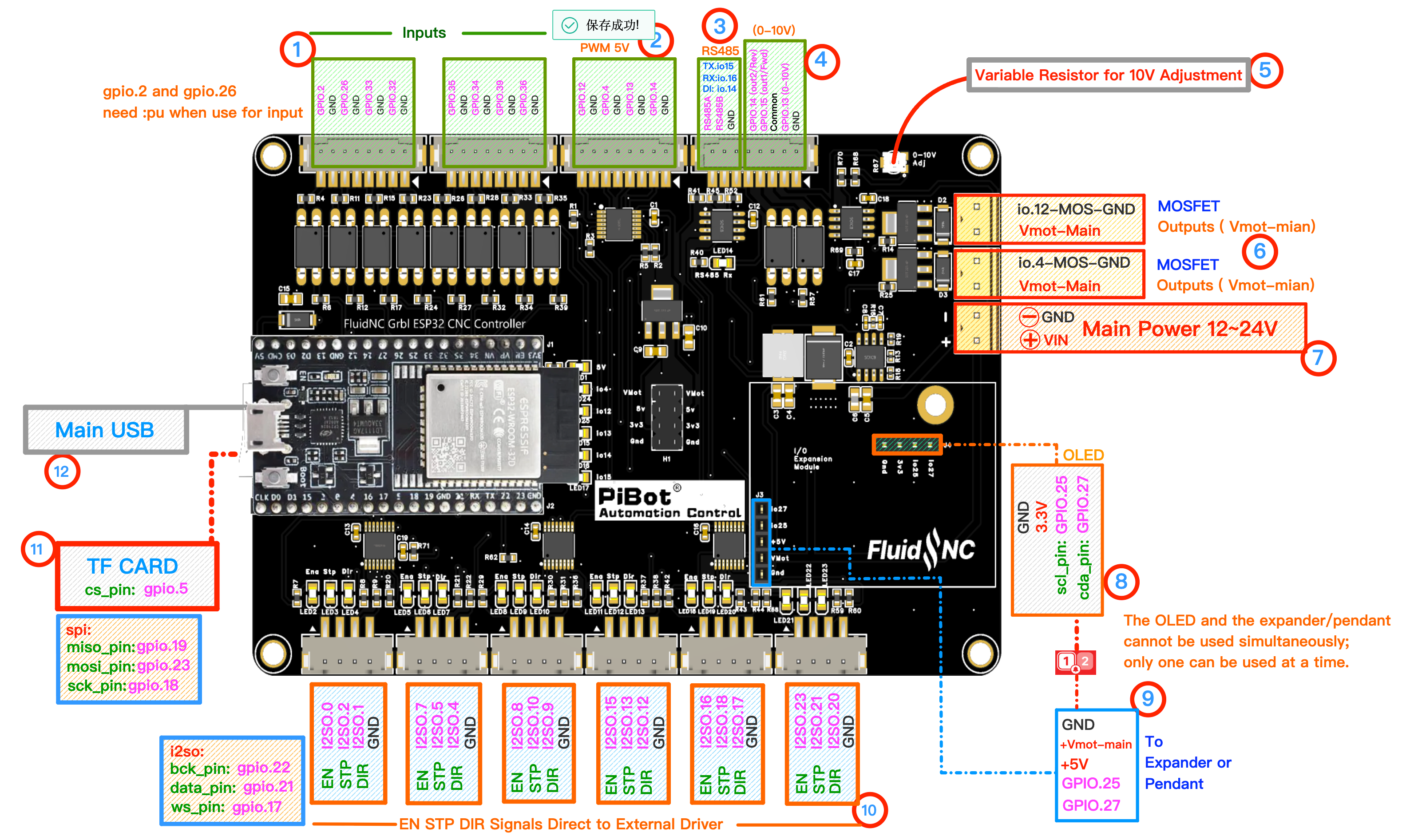
Use numbered area ④ for the 0–10 V/GND measurement and ⑤ for the adjustment trimmer. Click to enlarge.
🔧 How to Measure
Set the multimeter to DC voltage, auto-range.
RED (+) → 0–10 VBLACK (−) → GND
Red on 0–10 V, black on GND. Leave REV/FWD/COM disconnected during this analog-voltage test.
Follow these rows in order.
M6 T2→Select the 0–10 V spindle output (tool 2)
M3 S24000→calibrate to 10.0 Vfull scale
↻While S24000 is active: turn the 10 V adjustment trimmer slowly until the meter reads 10.0 V. Stop as soon as it reaches the target.
M3 S12500→about 5.0 Vmidpoint check
M3 S1000→about 0 Vbottom of configured range
M5→0.0 Voutput off
Shared GPIO note
Forward GPIO.15 and Reverse GPIO.14 share signals with the RS485 circuit. The supplied test YAML reserves them for RS485 and leaves Forward/Reverse as NO_PIN. This page tests only the GPIO.13 analog voltage.
✅ Pass: full scale can be calibrated to about 10 V, the midpoint is near 5 V, and the output returns to 0 V after
M5.pibot_cnc_laser_series/v47b/test_0_10v/start.txt · Last modified: by 127.0.0.1