
pibot_cnc_laser_series:v47b:pinout_reference:start
PiBot V4.7B — Pin Definition Overview
FluidNC / grblHAL · Plug-in classic ESP32 module · Six external-driver signal groups
FluidNC ports are assigned by the YAML file, so the software functions are configurable rather than permanently fixed.
The definitions on this page match the supplied V4.7B I/O-test YAML. Check your active YAML and board revision before wiring a machine.
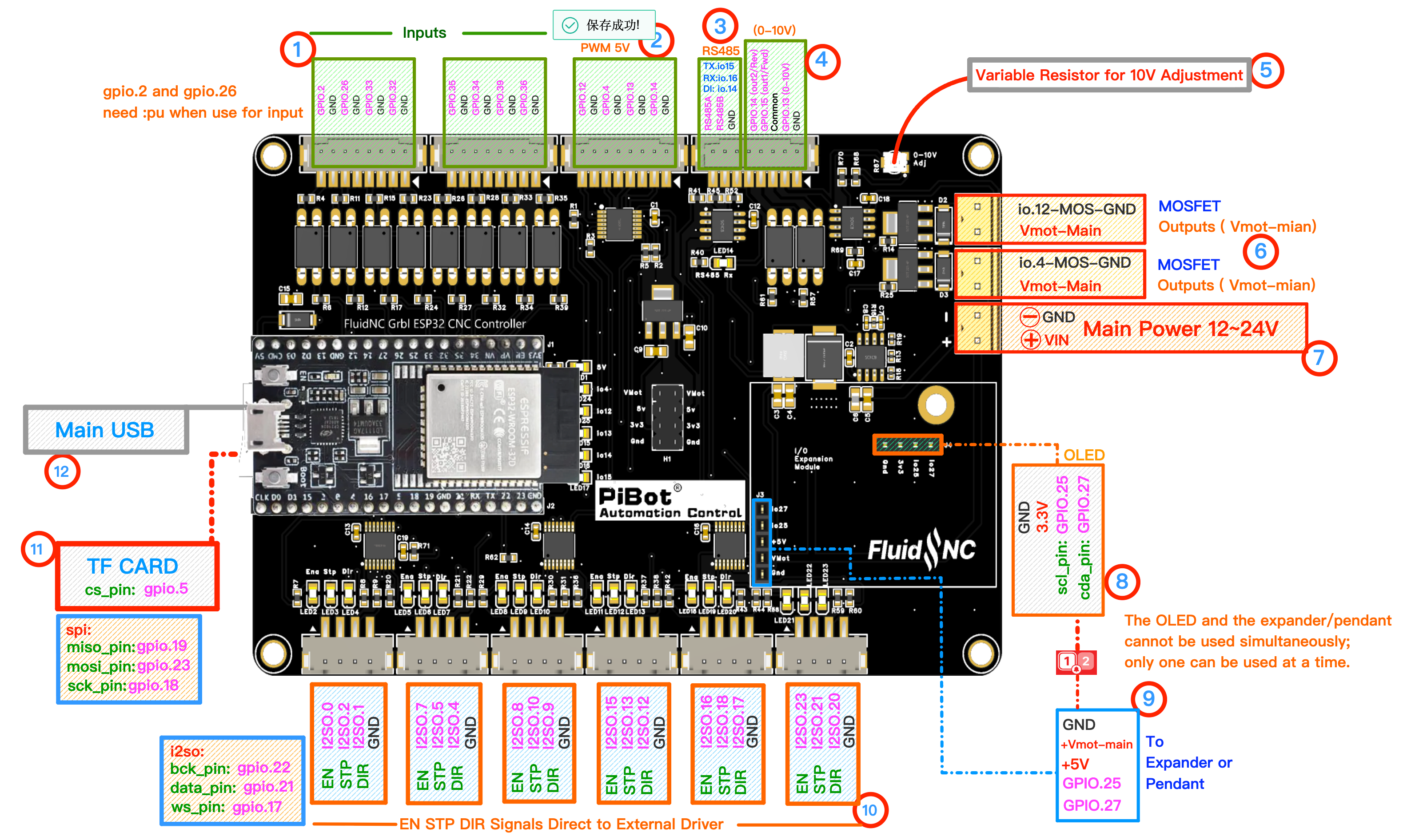
The numbered groups on the diagram correspond to the sections below. Click the diagram to view it at full size.
Quick Reference — UART Channels
| Channel | Physical Port | Pins in Test YAML | Typical Use |
|---|---|---|---|
| UART0 | Main USB 12 | On plug-in ESP32 module | Firmware, console and G-code sender |
| UART1 | RS485 3 | TX GPIO.15 · RX GPIO.16 · RTS GPIO.14 | Modbus VFD, 9600 8N1 in test YAML |
| UART2 | RJ12 9 | TX GPIO.25 · RX GPIO.27 when enabled | Compatible PiBot pendant / I/O expander |
Key to the Numbered Groups
💡 Tip: use the pinmap for connector location, the quick-reference tables for signal names, and the full YAML at the bottom of this page for the active test assignment.
Inputs Outputs Power Drivers Interface
1 Eight Input Channels Inputs
Eight signal inputs are available along the board edge. The supplied test YAML assigns them as follows.
| GPIO | Test function | GPIO | Test function |
|---|---|---|---|
| GPIO.2 | Probe, pull-up, active low | GPIO.26 | Tool setter, pull-up, active low |
| GPIO.33 | X limit − | GPIO.32 | X limit + |
| GPIO.35 | Y motor 0 limit | GPIO.34 | Y motor 1 limit |
| GPIO.39 | Z limit | GPIO.36 | A limit |
2 5 V Signal Outputs Outputs
- Header signals: GPIO.12, GPIO.4, GPIO.13 and GPIO.14, with GND.
- Test YAML: GPIO.4 = PWM tool 0, GPIO.12 = laser tool 1, GPIO.13 = 0–10 V generator.
- GPIO.4 and GPIO.12 also drive the matching MOSFET channels in ⑥; they are shared signals, not independent outputs.
3 RS485 Interface
- On-board MAX3485 transceiver with A/B terminal for Modbus RTU devices.
- Test YAML UART1: TX GPIO.15, RX GPIO.16, direction GPIO.14, 9600 baud, 8N1.
- If communication fails, first confirm baud, slave address and A/B polarity.
4 0–10 V Interface Outputs
- Analog output: GPIO.13; use the 0–10 V and GND terminals for the VFD analog input.
- Forward uses GPIO.15 and Reverse uses GPIO.14 with the contact common terminal.
- GPIO.14/15 are shared with RS485. The supplied test YAML leaves Forward/Reverse unassigned while UART1 is enabled.
5 10 V Adjustment Outputs
- Issue the maximum spindle command used by the YAML, then measure the analog output.
- Turn the trimmer slowly until full-scale output reaches the required voltage.
- Do not adjust by guesswork; keep the multimeter connected while calibrating.
6 MOSFET Outputs Outputs
- Two low-side channels:
io.12-MOS-GNDfollows GPIO.12 andio.4-MOS-GNDfollows GPIO.4. - Connect the load between Vmot-main (+) and the corresponding switched MOS-GND terminal.
- Maximum current: 1.5 A per channel. These outputs are for light loads only.
⚠ Do not connect a heavy load directly. Use the MOSFET output to control an external relay or suitable power driver; overloading the channel can burn the MOSFET.
7 Main Power 12–24 V DC Power
- Main carrier-board input: 12–24 V DC.
- Confirm VIN and GND polarity with a multimeter before power-on.
- USB alone powers the ESP32-side connection but is not enough for complete carrier-board testing.
8 OLED Interface Interface
- GND, 3.3 V, SCL GPIO.25, SDA GPIO.27.
- The test YAML enables a 128×64 OLED at I2C address
0x3C. - The OLED shares both signal pins with RJ12 ⑨; enable only one interface at a time.
9 RJ12 Pendant / Expander Interface
- Provides GND, Vmot-main, +5 V and UART2 signals on GPIO.25/GPIO.27 for a compatible PiBot pendant or I/O expander.
- The supplied YAML keeps UART2 commented while the OLED is active.
- Power off before connecting an accessory. Do not assume a telephone cable or third-party pinout is compatible.
⚠ RJ12 and OLED share GPIO.25/GPIO.27 and cannot be enabled at the same time.
10 Six External-Driver Signal Groups Drivers
Each connector provides EN / STP / DIR / GND. All six groups are intended for compatible external stepper drivers; V4.7B has no on-board StepStick sockets.
| Connector | Enable | Step | Direction | Test YAML use |
|---|---|---|---|---|
| X | I2SO.0 | I2SO.2 | I2SO.1 | X motor |
| Y | I2SO.7 | I2SO.5 | I2SO.4 | Y motor 0 |
| Z connector | I2SO.8 | I2SO.10 | I2SO.9 | Y motor 1 |
| A connector | I2SO.15 | I2SO.13 | I2SO.12 | Z motor |
| B connector | I2SO.16 | I2SO.18 | I2SO.17 | A motor |
| C connector | I2SO.23 | I2SO.21 | I2SO.20 | M7 / M8 / M64 P0 signal test |
11 microSD Interface
- SPI MISO GPIO.19, MOSI GPIO.23, SCK GPIO.18.
- Card select: GPIO.5.
- Insert or remove the card only when it is safe to do so and confirm it appears in FluidNC WebUI.
12 Main USB Interface
- The micro-USB connector is on the plug-in classic ESP32 module.
- Use a data-capable cable for FluidNC installation, serial console, boot logs and a USB G-code sender.
- If no serial port appears, try another data cable before troubleshooting the board.
Complete V4.7B Test YAML
📄 The complete test file is displayed below. Click the filename in the code block header to download it. This is an I/O-test profile, not a ready-to-run machine configuration.
- v47b-xyyza-standard-config.yaml
##############################################################################
## THIS EXAMPLE IS ONLY FOR I/O TESTING. MODIFY IT BEFORE USING IT ON A MACHINE. ####
#############################################################################

board: PiBot V47B
name:  PiBot V47B IO Test YAML

stepping:
  engine: I2S_STATIC
  idle_ms: 255
  pulse_us: 4
  dir_delay_us: 4
  disable_delay_us: 0
  segments: 6

###################################START TEST UART###################################
## uart0 main usb port
## uart1 RS485 tx rx
## uart2 RJ12 TX rx
#####################################################################################

## Begin expansion port uart and channel setup (test the rj12 port)
##uart2:
##  txd_pin: gpio.25
##  rxd_pin: gpio.27
##  baud: 1000000
##  mode: 8N1

##uart_channel2:
##  report_interval_ms: 75
##  uart_num: 2

###################################END TEST UART####################################

spi:
  miso_pin: gpio.19
  mosi_pin: gpio.23
  sck_pin: gpio.18

sdcard:
  card_detect_pin: NO_PIN
  cs_pin: gpio.5

i2so:
  bck_pin: gpio.22
  data_pin: gpio.21
  ws_pin: gpio.17

## Begin OLED
i2c0:
   sda_pin: gpio.27
   scl_pin: gpio.25

oled:
   i2c_num: 0
   i2c_address: 60
   width: 128
   height: 64
   radio_delay_ms: 1000
## END OLED

probe:
  pin: gpio.2:pu:low
  toolsetter_pin: gpio.26:pu:low
  check_mode_start: true
  hard_stop: false

coolant:
  mist_pin: I2SO.23
  flood_pin: I2SO.21

## m7 m8

user_outputs:
  digital0_pin: I2SO.20

##M64 P0 / on --  M65 P0 / off // M64 P1 on --  M65 P1 off

start:
  must_home: false

axes:
  shared_stepper_disable_pin: NO_PIN
  x:
    steps_per_mm: 800.000
    max_rate_mm_per_min: 5000.000
    acceleration_mm_per_sec2: 100.000
    max_travel_mm: 300.000
    soft_limits: false
    homing:
      cycle: 2
      positive_direction: false
      mpos_mm: 150.000
      feed_mm_per_min: 100.000
      seek_mm_per_min: 200.000
      settle_ms: 500
      seek_scaler: 1.100
      feed_scaler: 1.100

    motor0:
      limit_neg_pin: gpio.33:low
      limit_pos_pin: gpio.32:low
      limit_all_pin: NO_PIN
      hard_limits: false
      pulloff_mm: 1.000
      standard_stepper:
        step_pin: I2SO.2
        direction_pin: I2SO.1
        disable_pin: I2SO.0

######disable_pin:This is used if your controller uses individual disable pins for each driver.
######Most basic controllers use a common disable pin for all drivers and that is set elsewhere in the config file.
######You can invert the direction by changing the active state attribute (:high or :low)

  y:
    steps_per_mm: 800.000
    max_rate_mm_per_min: 5000.000
    acceleration_mm_per_sec2: 100.000
    max_travel_mm: 300.000
    soft_limits: false
    homing:
      cycle: 2
      positive_direction: false
      mpos_mm: 150.000
      feed_mm_per_min: 100.000
      seek_mm_per_min: 200.000
      settle_ms: 500
      seek_scaler: 1.100
      feed_scaler: 1.100

    motor0:
      limit_neg_pin: gpio.35:low
      limit_pos_pin: NO_PIN
      limit_all_pin: NO_PIN
      hard_limits: false
      pulloff_mm: 1.000
      standard_stepper:
        step_pin: I2SO.5
        direction_pin: I2SO.4
        disable_pin: I2SO.7

    motor1:
      limit_neg_pin: gpio.34:low
      limit_pos_pin: NO_PIN
      limit_all_pin: NO_PIN
      hard_limits: false
      pulloff_mm: 1.000
      standard_stepper:
        step_pin: I2SO.10
        direction_pin: I2SO.9
        disable_pin: I2SO.8

  z:
    steps_per_mm: 800.000
    max_rate_mm_per_min: 5000.000
    acceleration_mm_per_sec2: 100.000
    max_travel_mm: 300.000
    soft_limits: false
    homing:
      cycle: 2
      positive_direction: false
      mpos_mm: 150.000
      feed_mm_per_min: 100.000
      seek_mm_per_min: 200.000
      settle_ms: 500
      seek_scaler: 1.100
      feed_scaler: 1.100

    motor0:
      limit_neg_pin: gpio.39:low
      limit_pos_pin: NO_PIN
      limit_all_pin: NO_PIN
      hard_limits: false
      pulloff_mm: 1.000
      standard_stepper:
        step_pin: I2SO.13
        direction_pin: I2SO.12
        disable_pin: I2SO.15

  a:
    steps_per_mm: 800.000
    max_rate_mm_per_min: 5000.000
    acceleration_mm_per_sec2: 100.000
    max_travel_mm: 300.000
    soft_limits: false
    homing:
      cycle: 2
      positive_direction: false
      mpos_mm: 150.000
      feed_mm_per_min: 100.000
      seek_mm_per_min: 200.000
      settle_ms: 500
      seek_scaler: 1.100
      feed_scaler: 1.100

    motor0:
      limit_neg_pin: gpio.36:low
      limit_pos_pin: NO_PIN
      limit_all_pin: NO_PIN
      hard_limits: false
      pulloff_mm: 3.000
      standard_stepper:
        step_pin: I2SO.18
        direction_pin: I2SO.17
        disable_pin: I2SO.16

# Begin PWM
pwm:
  pwm_hz: 5000
#   direction_pin: NO_PIN
  output_pin: gpio.4
  enable_pin: NO_PIN
  disable_with_s0: false
  s0_with_disable: true
#   spinup_ms: 0
#   spindown_ms: 0
  tool_num: 0
  speed_map: 0=0.000% 10000=100.000%
  off_on_alarm: false

# Begin Laser
Laser:
  pwm_hz: 5000
  output_pin: gpio.12
  enable_pin: NO_PIN
  disable_with_s0: false
  s0_with_disable: true
  tool_num: 1
  speed_map: 0=0.000% 255=100.000%
  off_on_alarm: true

## Start 0-10V
10V:
  forward_pin: NO_PIN
  reverse_pin: NO_PIN
  pwm_hz: 5000
  output_pin: gpio.13
  enable_pin: NO_PIN
  direction_pin: NO_PIN
  disable_with_s0: false
  s0_with_disable: true
  spinup_ms: 0
  spindown_ms: 0
  tool_num: 2
  speed_map: 0=0.000% 1000=0.000% 24000=100.000%
  off_on_alarm: false

## Start only for test the RS485chip communication
uart1:
  txd_pin: gpio.15
  rxd_pin: gpio.16
  rts_pin: gpio.14
  baud: 9600
  mode: 8N1

ModbusVFD:
  uart_num: 1
  modbus_id: 1
  debug: 0
  poll_ms: 250
  retries: 5
  spinup_ms: 6000
  spindown_ms: 6000
  tool_num: 3
  speed_map: 0=0.00% 24000=100.00%
  off_on_alarm: false
  atc:
  m6_macro:
  s0_with_disable: false
  disable_with_s0: false
  model: Huanyang
  min_RPM: 6000
  max_RPM: 24000
  cw_cmd: 03 01 01 > echo
  ccw_cmd: 03 01 11 > echo
  off_cmd: 03 01 08 > echo
  set_rpm_cmd: 05 02 rpm*100/60 > echo
  get_min_rpm_cmd: 01 03 0b 00 00 > 01 03 0B minRPM*60/100
  get_max_rpm_cmd: 01 03 05 00 00 > 01 03 05 maxRPM*60/100
  get_rpm_cmd: 04 03 01 00 00 > 04 03 01 rpm*60/100
pibot_cnc_laser_series/v47b/pinout_reference/start.txt · Last modified: by 127.0.0.1