
0 Introduction - PiBot V4.7B Controller
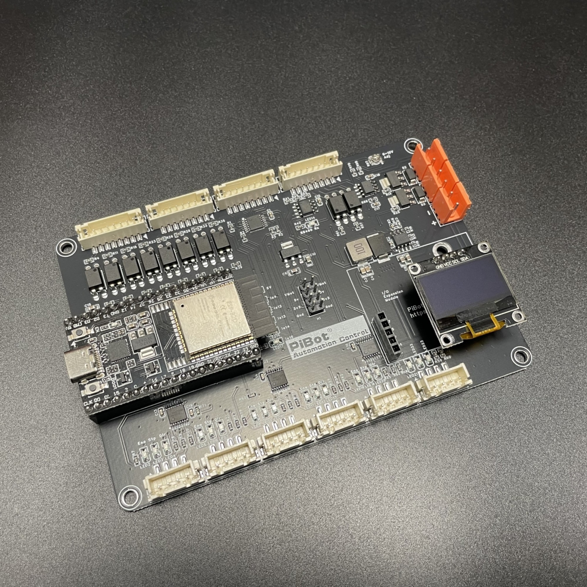
What Is the V4.7B?
The PiBot V4.7B is a six-output CNC and laser controller carrier board for a plug-in classic ESP32 DevKitC / ESP32-WROOM-32 module. It reads G-code through FluidNC or grblHAL and provides external Step / Dir / Enable signals, eight input channels, PWM and laser outputs, 0-10 V spindle control, Modbus RS485, two MOSFET power outputs, microSD, OLED and an RJ12 pendant/expander port.
Like V5.77, the processor module is replaceable. Unlike V4.96 Pro, V4.7B has no on-board StepStick sockets, no driver-voltage jumper and no on-board SPI-driver routing. All six motor groups are intended for compatible external drivers.
About the Supplied YAML
v47b-xyyza-standard-config.yaml is an I/O test configuration for FluidNC. It maps the six driver connectors as X, Y, a second Y motor, Z, A, and a final C-connector signal test. It also enables the board's inputs, SD card, OLED, PWM, laser, 0-10 V and RS485 functions so they can be checked in a controlled sequence.
Quick Facts
| Item | V4.7B |
|---|---|
| Processor | Replaceable 38-pin classic ESP32 DevKitC / ESP32-WROOM-32 module; not an ESP32-S3 module |
| Firmware | FluidNC test workflow; official grblHAL PiBot 6-axis I2S board map is also available |
| Motor outputs | 6 external EN / STP / DIR / GND groups using I2S shift-register outputs; no on-board drivers |
| Inputs | 8 channels: GPIO 2, 26, 33, 32, 35, 34, 39 and 36 |
| Spindle / laser | 5 V PWM, laser PWM, 0-10 V analog, Forward/Reverse contacts and Modbus RTU over RS485 |
| MOSFET outputs | 2 low-side channels, 1.5 A maximum per channel. Use an external relay or suitable power driver for heavier loads |
| Storage / display | microSD and 128x64 I2C OLED |
| Expansion | RJ12 pendant or I/O expander. OLED and RJ12 share GPIO 25/27 and cannot operate simultaneously |
| Power | 12-24 V DC main input required for carrier-board testing; USB alone is insufficient |
Recommended Tutorial Order
- Read the Pinout Reference.
- Complete every item in 2 Checklist Before Use with the controller on a bench.
- Run the optional RJ12 and RS485 tests only when you have the required adapter or accessory.
- Use the Hardware Connection pages when creating a machine-specific YAML and wiring the controller into the machine.