
pibot_cnc_laser_series:v47b:connect_limit_switches:start
4.1 Connect Limit Switches and Sensors
Eight optocoupled signal/GND inputs on V4.7B
Power off before wiring. V4.7B does not have the V5.77/V4.96 three-pin SW-VCC input system. Follow the V4.7B signal/GND pin map and do not apply main VIN to an input.
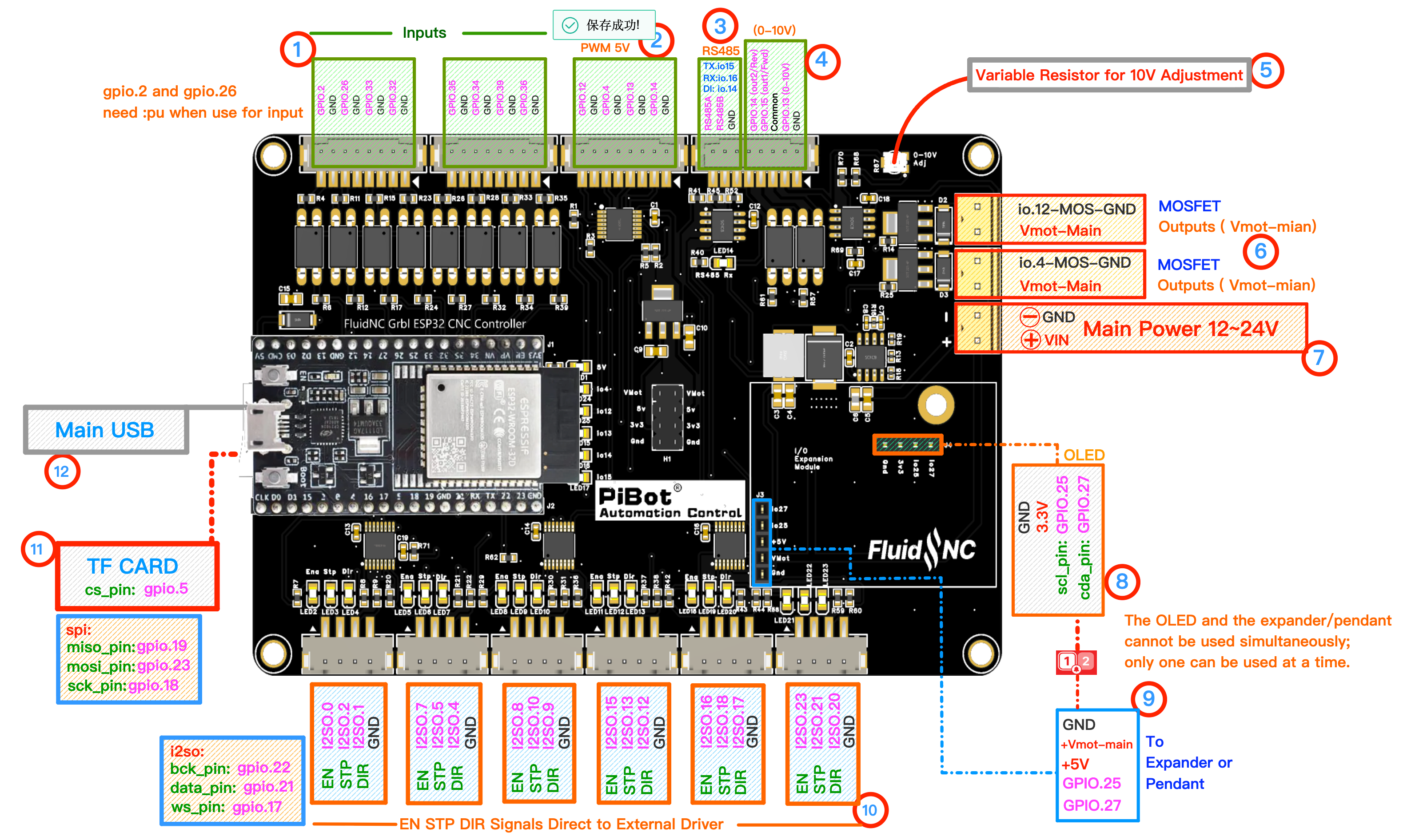
Numbered area 1 contains the eight V4.7B input signal/GND pairs.
Choose the interface
- Mechanical contact: use a board-compatible 5 V input circuit and choose normally-closed wiring where practical so a broken cable can be detected.
- Powered sensor: confirm its output type and voltage. Use a suitable isolated interface or level converter when it cannot provide a safe 5 V logic signal.
- Industrial 12-24 V sensor: do not connect its output directly unless the exact V4.7B input electrical rating and sensor topology have been verified. An optically isolated interface is the safest general solution.
Commission one input at a time
- Start with hard limits disabled and motor power disconnected.
- Wire one sensor and verify idle/triggered states using
$Limits. - Set the correct pin assignment and polarity in the machine YAML.
- Check for chatter, noise and false triggers before enabling hard limits or homing.
- Repeat for the remaining inputs; route sensor cables away from motor and spindle wiring.
The factory YAML maps GPIO 2/26 as probe/tool setter, 33/32 as X-/X+, 35/34 as dual-Y limits, and 39/36 as Z/A. Your machine YAML may assign them differently.
Acceptance check: each input changes cleanly and independently, uses the intended polarity, and a disconnected normally-closed circuit produces the expected fault state.
pibot_cnc_laser_series/v47b/connect_limit_switches/start.txt · Last modified: by 127.0.0.1