0 Introduction - PiBot V5.88 Ultra
What is the V5.88 Ultra?
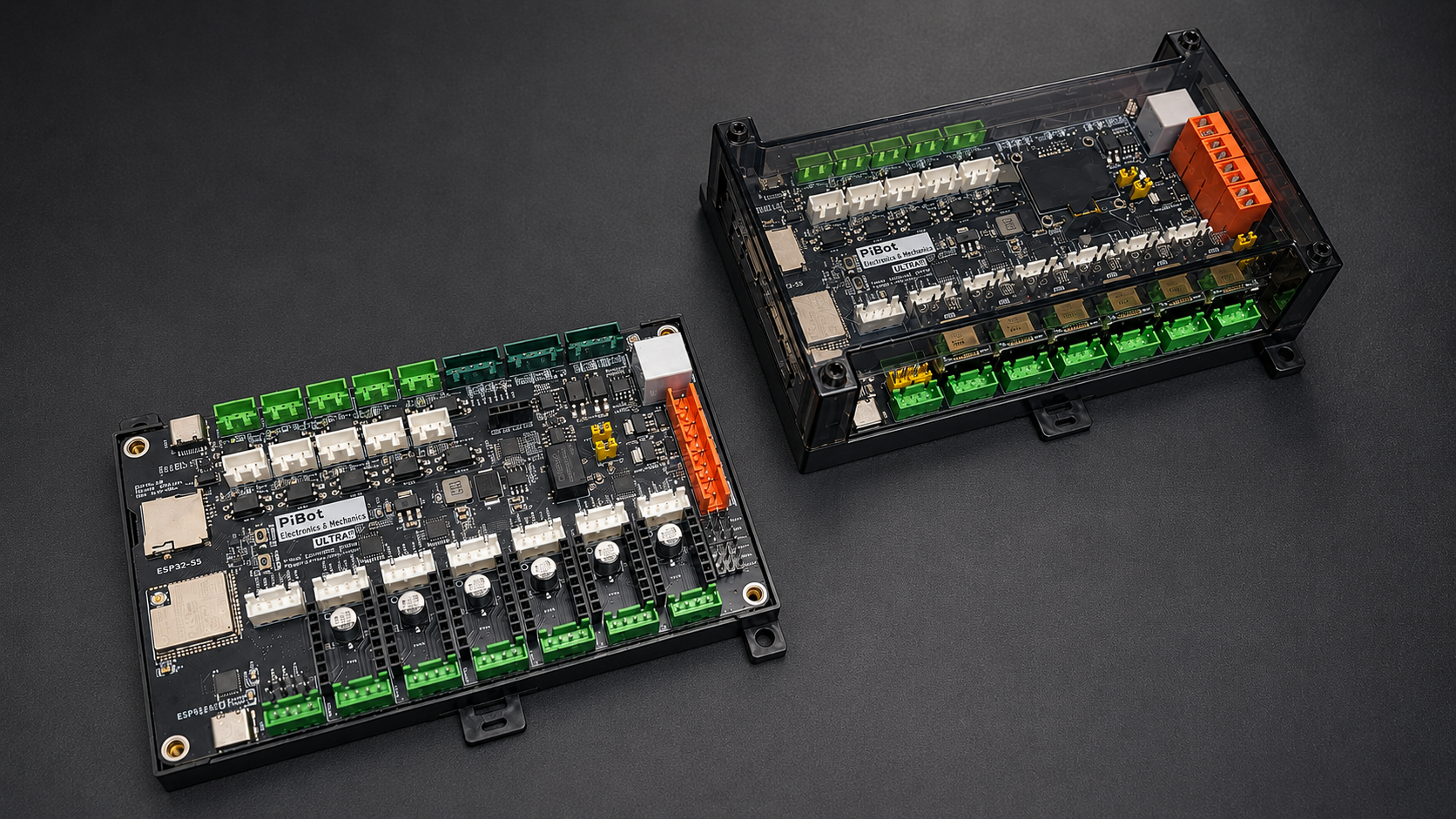
The PiBot Controller V5.88 Ultra is a 6+1 axis CNC motion controller built around the Espressif ESP32-S3-WROOM-1U-N8R8 (dual-core LX7, 240 MHz, 8 MB Flash + 8 MB octal PSRAM, external IPEX antenna). It runs FluidNC out of the box and controls routers, lasers, plasma cutters, and mills — reading G-code over USB, WiFi, or SD card, driving the stepper motors, controlling the spindle (PWM / 0–10 V / Modbus RTU), and handling limit switches, probes, the e-stop, and accessories.
This tutorial section of the wiki is the technical handbook for the board: pinout, wiring, step-by-step testing, and configuration. The product page on the store describes what the board is and what it can build; everything about how to actually use it lives here, and is updated continuously.
Quick Facts
| Item | Specification |
|---|---|
| MCU | ESP32-S3-WROOM-1U-N8R8 — dual-core LX7, 240 MHz, 8 MB Flash, 8 MB octal PSRAM, IPEX antenna |
| Firmware | FluidNC (supported). grblHAL: port in development, not yet released — see the grblHAL chapter for current status |
| Axes | 6 + 1 (X, Y, Z, A, B, C + expansion axis); each main axis has both an on-board Pololu socket and an external Step/Dir/Enable output |
| Driver support | A4988, DRV8825, TMC2208, TMC2209, TMC2130, TMC5160 (SPI mode with per-axis chip select on all 6 axes); external drivers at 5 V signal levels |
| Inputs | 10× opto-isolated (TLP521GB-S + PSM712-ES TVS); switch supply jumper-selectable Vin or +5 V |
| Outputs | 4× 5 V PWM/digital (GPIO.4/5/45/46); 2× MOSFET (io.4 / io.5, switched by GPIO.4/GPIO.5, flyback diodes, 500 mA max per channel); 1× 0–10 V analog with calibration trim; on-board relay output |
| RS485 | Galvanically isolated (ADUM3201 + B0505XT + SN65HVD3082E) for Modbus RTU VFD spindles |
| Peripherals | OLED (I2C), RJ12 pendant (independent UART, 1,000,000 baud), I/O expander socket — all usable simultaneously |
| USB / Storage | 2× USB-C (CP2102 + native USB CDC); micro SD card |
| Power | 12–24 V DC, reverse-polarity protected on the main input. Do not exceed 24 V — the LM358 and SW-VCC input circuit are limited to 24 V even though the regulator itself is rated higher |
| PCB | 4-layer, 146.5 × 87 mm, DIN-rail enclosure shared with V4.96 Pro; 42 status LEDs |
How to Use This Tutorial
The tutorial is organized by task. For a new board, work through it in this order — each stage builds on the one before it:
- 1 — Get to know the board. Start with the Pinout Reference to learn every connector, terminal, and jumper. Keep it open as a reference throughout the rest of the tutorial.
- 2 — Bench-commission with the Check List. The Check List before Use is the core of the tutorial. With the board on the bench (not yet in your machine), set the jumpers and power on, connect to WiFi and the WebUI, flash the firmware and upload the YAML, then test every subsystem in order — endstops, motor signals, spare I/O, MOSFET outputs, and the PWM / laser / 0–10 V spindle outputs. Each step has a clear pass/fail check. A separate Advanced Tests section then covers the optional, tool-dependent checks (secondary USB, RJ12 port, RS485). If it's your first PiBot board, start here, and do not skip the basic steps.
- 3 — Wire it into your machine. The Hardware Connection reference covers every wiring variant: limit switches (5 V / 12–24 V / mixed), stepper drivers (on-board / external / SPI / mixed), relay, pendant, I/O expander, and spindles.
- 4 — Software compatibility. The Software Introduction lists which G-code senders and tools (LightBurn, LaserGRBL, Candle, UGS, OpenBuilds CONTROL, etc.) are known to work with each firmware. It is a compatibility reference only — for how to use any third-party software, please refer to that software's own documentation.
In short: get to know the board → bench-commission it with the Check List → wire it into your machine. The Check List is the heart of the tutorial.
Before You Power On - The Short Version
The full commissioning procedure is the Check List chapter. These rules prevent the most common damage during that process:
- Use 12–24 V, not 5 V — and never exceed 24 V. The V5.88 Ultra needs 12 V or 24 V at the power terminal (24 V recommended); 5 V is not enough to run the board, and over 24 V will damage on-board components. Verify polarity with a multimeter before connecting.
- Set the jumpers first. VDDSEL (driver logic voltage — default
3.3V, required for SPI/TMC drivers; select5Vonly for 5 V-logic external drivers) and the SW-VCC input supply, before installing any driver module. - Match driver module orientation to the socket silkscreen — a module inserted rotated 180° is destroyed at power-on.
- Set driver current before the first motion test.
- Never hot-plug drivers, motors, the OLED, or the pendant while the board is powered.
Firmware Status
- FluidNC — supported and pre-flashed. Configuration is a single YAML text file; the WebUI runs in any browser on the same network. Official docs: wiki.fluidnc.com.
- grblHAL — a port for the V5.88 Ultra is in development and not yet released. No release date is committed; availability will be announced in the grblHAL chapter and on the store. Until then, treat the V5.88 Ultra as a FluidNC controller.
Getting Help
If you get stuck, check the FAQ chapter first. When contacting us through the store messaging system, include: board version, firmware version, your YAML file, a photo of your wiring, and the boot log from the USB console — with that set of information, most cases are resolved in a single round.