2.7 Test Extra I/O
Check List · Step 7 of 12 · Test the six configurable Extra I/O / I2SO signals as ordinary outputs
🎯 Objective
This step checks the six configurable Extra I/O / I2SO signals on the two 4-pin headers at the lower-right edge of the board. The test YAML uses them as ordinary FluidNC user outputs P0 through P5. In a machine configuration, the same six signals may instead form two additional Step / Dir / Enable motor groups, bringing the board from six dedicated axes to a maximum of eight. These uses are mutually exclusive. You will switch each output on and off and watch its indicator LED. No external wiring is required.
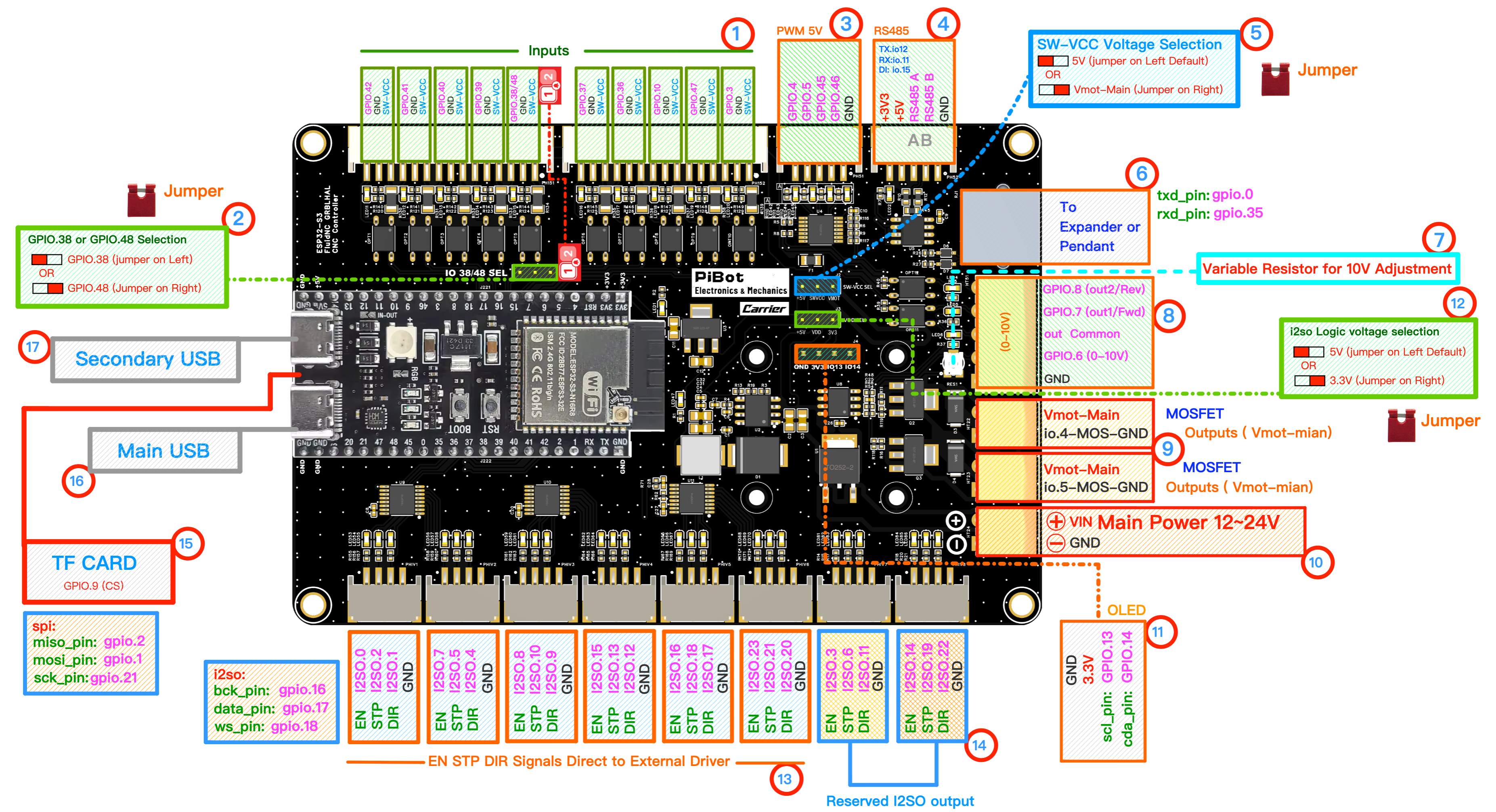
Item 14 marks the two configurable Extra I/O groups. Each group provides three I2SO signals and GND. (click to enlarge)
🧪 How to Test
Open the FluidNC WebUI and send the ON and OFF command for each channel. Test one channel at a time.
P0
→
M64 P0 ON / M65 P0 OFF — I2SO.3
P1
→
M64 P1 ON / M65 P1 OFF — I2SO.6
P2
→
M64 P2 ON / M65 P2 OFF — I2SO.11
P3→
M64 P3 ON / M65 P3 OFF — I2SO.14P4→
M64 P4 ON / M65 P4 OFF — I2SO.19P5→
M64 P5 ON / M65 P5 OFF — I2SO.22✅ Pass: each corresponding output LED turns on with
M64 and off with M65. With the I2SO logic jumper set to 5 V, an optional multimeter check from signal to GND should read approximately 5 V when on and 0 V when off.⚠ Important: these are logic signals, not load-power outputs. Use a suitable driver, relay interface, or optocoupler for external loads. Their high level follows the item 12 I2SO voltage jumper (5 V by default, or 3.3 V).