0 Introduction - PiBot V5.77 Carrier
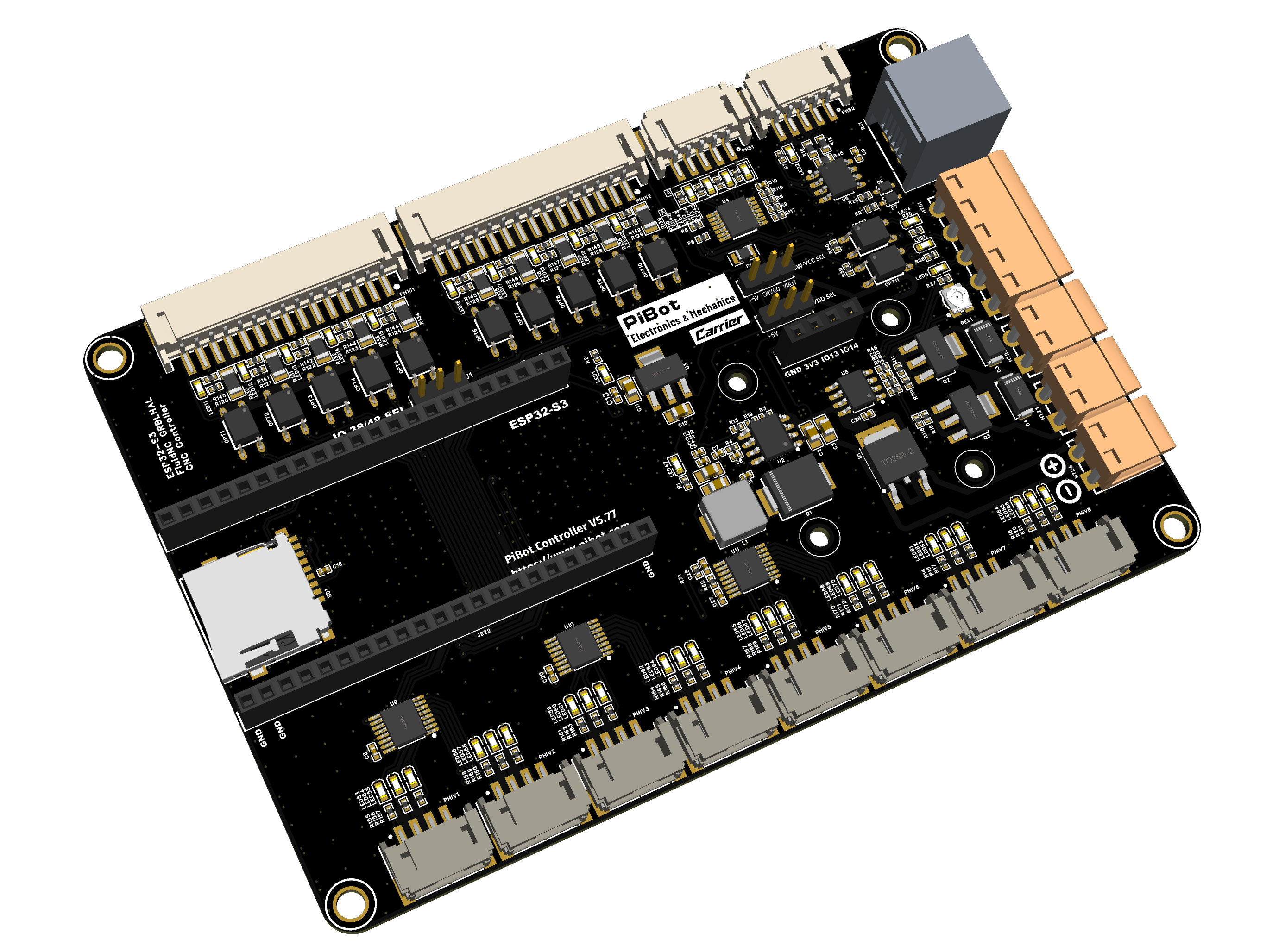
What is the V5.77 Carrier?
The PiBot Controller V5.77 Carrier is a 6+2-axis CNC motion controller supporting up to eight axes, built around a plug-in ESP32-S3 module (dual-core LX7, 240 MHz). It supports FluidNC and grblHAL and controls routers, lasers, plasma cutters, and mills — reading G-code over USB, WiFi, or SD card, and handling limit switches, probes, spindles (PWM / 0–10 V / Modbus RTU), and accessories.
Like the V4.7B, the V5.77 is a carrier board using a plug-in controller module; the V5.77 module is an ESP32-S3. There are no on-board stepper drivers. Six dedicated Step / Dir / Enable groups are brought out on PH2.0 connectors for external drivers. The six signals on the Extra I/O headers can optionally be configured as two more Step / Dir / Enable motor groups, or they can remain ordinary outputs; those two uses are mutually exclusive. The ESP32-S3 module itself is replaceable, the RS485 transceiver is a standard (non-isolated) chip, and the PCB is a cost-optimized 2-layer design.
This tutorial section of the wiki is the technical handbook for the board: pinout, wiring, step-by-step testing, and configuration. The product page on the store describes what the board is and what it can build; everything about how to actually use it lives here, and is updated continuously.
About This Wiki and the Test YAML
The YAML configuration provided with this board is an IO-test configuration. Its purpose is to exercise as many of the board's functions as possible — all 6 main axes, every input, the MOSFET outputs, PWM, laser, 0–10 V, RS485, the OLED, the SD card, and the RJ12 port — so that you can verify the whole board on the bench with one file. A real machine will almost never use all of these at once.
FluidNC is configured through a single, flexible YAML text file, so this all-in-one test setup is easy to build; grblHAL configurations are comparatively fixed, which does not lend itself to the same kind of catch-all file. The test YAML is our compromise between the two — it is a verification tool and a reference, not a ready-made machine profile. When you wire the board into your machine, take the sections you need from it and adapt them to your own requirements.
Quick Facts
| Item | Specification |
|---|---|
| MCU | Plug-in ESP32-S3 module — dual-core LX7, 240 MHz. Note: early modules use GPIO.48 for the on-board RGB LED (leaving IO38 free); newer modules use GPIO.38 (leaving IO48 free). A jumper on the board selects which one reaches the input header — the default YAML uses IO38 |
| Firmware | FluidNC and grblHAL. FluidNC configuration uses a YAML text file; grblHAL requires a compatible ESP32-S3 build and V5.77 board map |
| Axes | 6 dedicated + 2 configurable, up to 8 axes total. Six main axes (X, Y, Z, A, B, C) use dedicated PH2.0 Step / Dir / Enable connectors. The six Extra I/O / I2S shift-register signals (I2SO) can instead form two additional Step / Dir / Enable groups, or be used as ordinary outputs; the same signals cannot perform both functions at once. External drivers only. I2SO signal level is jumper-selectable: 5 V (default) or 3.3 V |
| Drivers | External stepper drivers only — no on-board driver sockets |
| Inputs | 10× 3-pin inputs (signal / GND / SW-VCC): GPIO.36/37/38⁄48/39/40/41/42/47/10/3; switch supply jumper-selectable +5 V (default) or Vin |
| Outputs | 4× 5 V PWM/digital (GPIO.4/5/45/46); 2× MOSFET (io.4 / io.5, switched by GPIO.4/5, 1.5 A maximum per channel); 1× 0–10 V analog with adjustment trimmer, plus spindle Fwd/Rev (GPIO.7/8) |
| RS485 | Standard on-board transceiver (non-isolated) for Modbus RTU VFD spindles |
| Peripherals | OLED (I2C, 128×64), RJ12 port for pendant or I/O expander (independent UART, 1,000,000 baud) |
| USB / Storage | 2× USB-C (main + secondary); micro SD card |
| Power | 12–24 V DC on the main power terminal. Verify polarity with a multimeter before connecting |
| PCB | 2-layer, cost-optimized design |
How to Use This Tutorial
The tutorial is organized by task. For a new board, work through it in this order — each stage builds on the one before it:
- 1 — Get to know the board. Start with the Pinout Reference to learn every connector, terminal, and jumper. Keep it open as a reference throughout the rest of the tutorial.
- 2 — Bench-commission with the Check List. The Check List before Use is the core of the tutorial. With the board on the bench (not yet in your machine), set the jumpers and power on, connect to WiFi and the WebUI, flash the firmware and upload the YAML, then test every subsystem in order — endstops, motor signals, spare I/O, MOSFET outputs, and the PWM / laser / 0–10 V spindle outputs. Each step has a clear pass/fail check. A separate Advanced Tests section then covers the optional, tool-dependent checks (secondary USB, RJ12 port, RS485). If it's your first PiBot board, start here, and do not skip the basic steps.
- 3 — Wire it into your machine. The Hardware Connection reference covers every wiring variant: limit switches (5 V / 12–24 V / mixed), external stepper drivers, pendant, I/O expander, and spindles.
- 4 — Software compatibility. The Software Introduction lists which G-code senders and tools (LightBurn, LaserGRBL, Candle, UGS, OpenBuilds CONTROL, etc.) are known to work with each firmware. It is a compatibility reference only — for how to use any third-party software, please refer to that software's own documentation.
In short: get to know the board → bench-commission it with the Check List → wire it into your machine. The Check List is the heart of the tutorial.
Before You Power On - The Short Version
The full commissioning procedure is the Check List chapter. These rules prevent the most common damage during that process:
- Use 12–24 V, not 5 V. The V5.77 Carrier needs 12 V or 24 V at the main power terminal; 5 V is not enough to run the board. Verify polarity with a multimeter before connecting.
- Install the ESP32-S3 module first and check its orientation against the silkscreen — a module inserted the wrong way can be damaged at power-on.
- Set the jumpers first: the SW-VCC input supply (default +5 V), the IO38 / IO48 selection for your module revision, and the I2SO signal level (default 5 V) — before wiring any external driver or switch.
- Never hot-plug the ESP32-S3 module, drivers, motors, the OLED, or the pendant while the board is powered.
Firmware Status
- FluidNC — supported. Configuration is a single YAML text file; the WebUI runs in any browser on the same network. Official docs: wiki.fluidnc.com.
- grblHAL — V5.77 supports grblHAL, but grblHAL configurations are comparatively fixed, so the all-in-one FluidNC test YAML used in this tutorial does not apply to it. Use a compatible ESP32-S3 build and V5.77 board map.
Getting Help
If you get stuck, check the FAQ chapter first. When contacting us through the store messaging system, include: board version, firmware version, your YAML file, a photo of your wiring, and the boot log from the USB console — with that set of information, most cases are resolved in a single round.