2.6 Test Motor Signal LEDs
Check List · Step 6 of 12 · Verify the XYYZA EN / STP / DIR signals without motors
ℹ️
Objective: jog one software axis at a time and confirm the corresponding physical driver connector indicators respond according to the V4.7B XYYZA test mapping.
⚠️
Keep all external drivers and motors disconnected. This step checks only the controller’s signal LEDs and logic outputs.
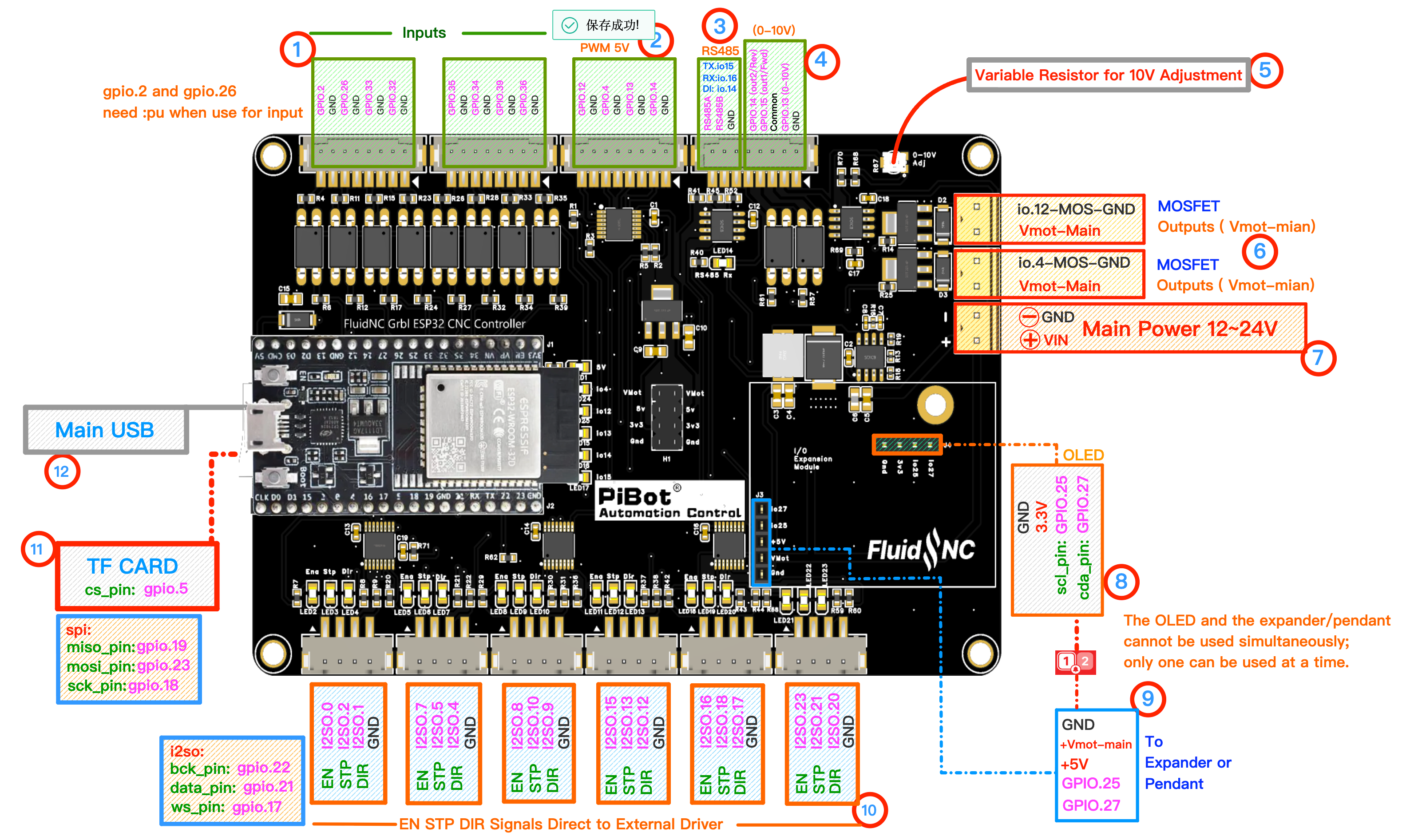
Watch numbered area ⑩. Each physical connector has EN, STP, DIR and GND. Click to enlarge.
1
Understand the Test Mapping
| WebUI jog | Physical connector | Expected indicators |
|---|---|---|
| X + / − | X | X STP activity; X DIR changes |
| Y + / − | Y and Z | Both Y-motor groups pulse together |
| Z + / − | A | A connector carries Z test signals |
| A + / − | B | B connector carries A test signals |
| C connector | C | Tested separately in Step 2.7 |
💡 This XYYZA arrangement is a factory I/O test. It does not force your final machine to use the same mapping.
2
Open Jog and Use Safe Settings
- Confirm again that no driver or motor is connected.
- Open WebUI Jog.
- Clear an Alarm only after confirming the bench is safe.
- Select a small distance such as
1 mmand a low feed rate.
3
Jog from Top to Bottom
X
Jog X+ then X−
Watch X STP and DIR
Watch X STP and DIR
Y
Jog Y+ then Y−
Watch both Y and Z connectors
Watch both Y and Z connectors
Z
Jog Z+ then Z−
Watch the physical A connector
Watch the physical A connector
A
Jog A+ then A−
Watch the physical B connector
Watch the physical B connector
4
Confirm EN, STP and DIR
- STP shows activity only while that axis is moving.
- DIR changes state between positive and negative jogs.
- EN remains in the state defined by the active YAML.
- If an indicator is hard to see, measure that signal relative to the connector GND without shorting adjacent pins.
✓
Expected Results
- X responds at X.
- Y responds at both Y and Z.
- Z responds at A.
- A responds at B.
- The expected DIR indication reverses for each positive/negative jog.