2.5 Test Probe and Input Signals
Check List · Step 5 of 12 · Verify all eight input channels one at a time
ℹ️
Objective: operate one input at a time and confirm that only the matching FluidNC status changes, then returns to inactive when released.
⚠️
Low-voltage test only: use the signal pin and its adjacent GND shown on the V4.7B pinmap. Never apply Vmot-main or guess a connector.
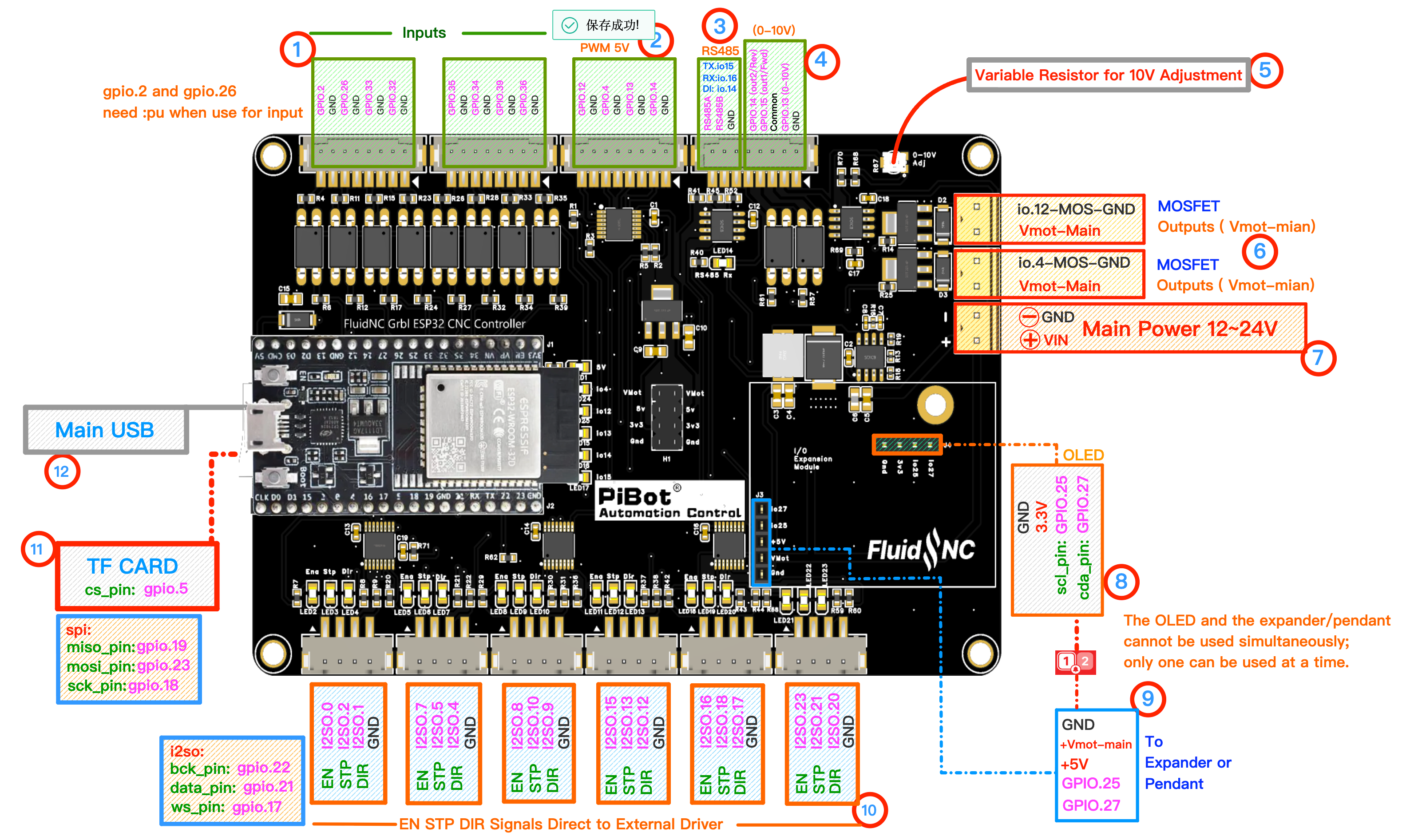
Use numbered area ① Inputs. Each GPIO has its own adjacent GND. Click to enlarge.
Selected GPIO input⇄Adjacent GNDone channel at a time
1
Open the Input Status
- Keep motors and external drivers disconnected.
- Open FluidNC WebUI Console.
- Send
$Limitsand record the inactive state. - Keep the console visible while testing.
2
Test Each GPIO / GND Pair
| GPIO | Function in test YAML | What to confirm |
|---|---|---|
| GPIO.2 | Probe | Probe changes only |
| GPIO.26 | Tool setter | Tool setter changes only |
| GPIO.33 | X limit − | X− changes only |
| GPIO.32 | X limit + | X+ changes only |
| GPIO.35 | Y motor 0 limit | First Y input changes |
| GPIO.34 | Y motor 1 limit | Second Y input changes |
| GPIO.39 | Z limit | Z input changes only |
| GPIO.36 | A limit | A input changes only |
- Bridge or operate only the selected input and its adjacent GND.
- Send
$Limitsagain or watch the WebUI status. - Remove the bridge and confirm the input returns to inactive before moving to the next row.
3
Check Polarity and Independence
- The supplied YAML uses active-low definitions; GPIO.2 and GPIO.26 also use internal pull-ups.
- If a machine sensor works backward later, correct its wiring or polarity in the machine-specific YAML.
- Two unrelated inputs changing together indicates wiring or configuration that must be corrected before continuing.
✓
Expected Results
- All eight inputs respond independently.
- Each input reports the function listed in the table.
- Each returns to inactive when the bridge or switch is released.
- No other channel changes unexpectedly.