4.2 Connect External Stepper Drivers
Hardware Connection · Six EN / STP / DIR / GND signal groups for compatible external drivers
ℹ️
What this page covers: V4.7B sends logic-level Enable, Step and Direction signals to an external driver. The external driver supplies motor phase current and connects to the motor.
⚠️
Never connect a stepper motor directly to X/Y/Z/A/B/C. V4.7B has no on-board StepStick sockets. Always power off the controller and every driver before changing signal, motor or power wiring.
PiBot V4.7B
EN · STP · DIR · GND
EN · STP · DIR · GND
➜
External Driver
PUL · DIR · ENA
PUL · DIR · ENA
➜
Stepper Motor
A+ · A− · B+ · B−
A+ · A− · B+ · B−
1
Understand One V4.7B Driver Connector
ENSTPDIRGND
| V4.7B signal | External-driver function | Check in the driver manual |
|---|---|---|
| EN | Enable | ENA polarity and whether Enable may be left unused |
| STP | Pulse / Step / CLK | Input voltage and minimum pulse width |
| DIR | Direction | Input voltage, polarity and setup time |
| GND | Logic reference | Common-negative/common-cathode compatibility |
- Complete 2.6 Test Motor Signal LEDs before connecting any driver.
- Use one driver first. Add the remaining axes only after the first short jog works correctly.
EXAMPLE A
Standard TB / DM External Driver
2
Connect a 5 V-Compatible Common-Negative Input
The following diagram applies to common TB6600, DM420, DM542, DM556 and similar drivers when their optocoupler inputs accept the V4.7B logic level and are wired with a common negative.
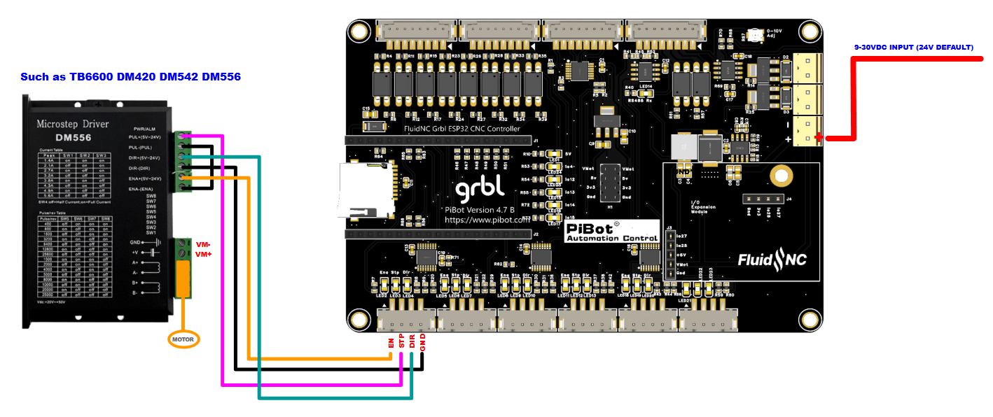
V4.7B EN/STP/DIR/GND to a standard common-negative external driver. Click for the full-size diagram.
| V4.7B | Driver terminal shown |
|---|---|
| EN | ENA+ / EN+(5–24 V) |
| STP | PUL+ / PULSE+ |
| DIR | DIR+ |
| GND | ENA−, PUL− and DIR− common |
⚠️
Driver terminal names and input circuits vary. If your driver requires common-anode/common-positive wiring, differential line signals or a higher input current, do not copy this diagram blindly; follow that driver’s manual or use a suitable interface.
3
Wire Driver Power and Motor Phases
- Connect the motor supply to the external driver’s own power terminals, with the polarity and voltage required by that driver.
- Identify the motor’s two winding pairs with its datasheet or an ohmmeter.
- Connect one winding to A+/A− and the other to B+/B−.
- Never plug or unplug a motor while the driver is powered.
- Set phase current and microstepping before the first powered movement; begin with conservative current and acceleration.
EXAMPLE B
PiBot SilentStep Driver Modules
4
Use the PiBot EN / STP / DIR / GND Interface
The PiBot SilentStep modules can use the same four-signal groups through their matching cable interface. The example below shows X, Y1, Y2 and Z connections.
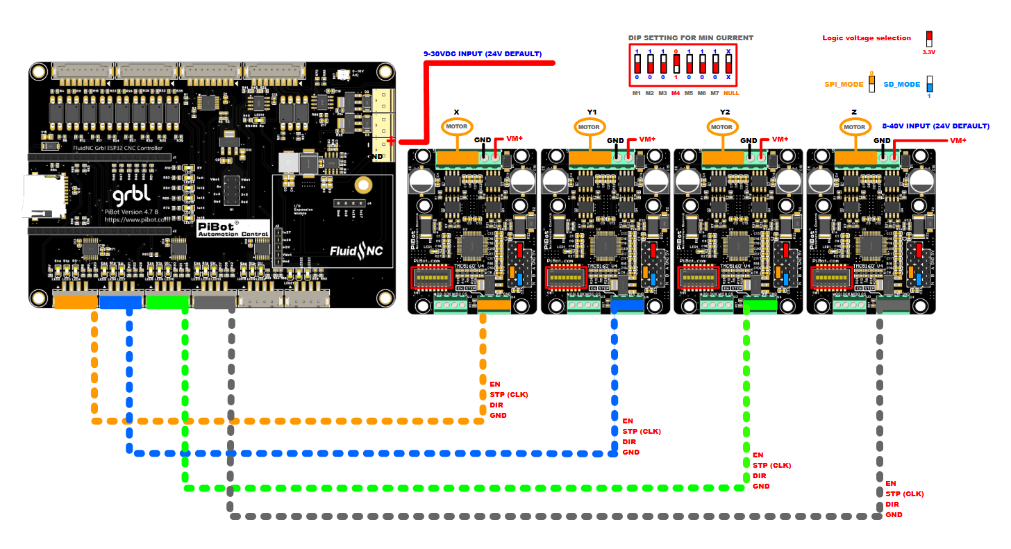
V4.7B connected to PiBot SilentStep modules. Verify the driver-module revision, logic-voltage selector, current DIP settings and power range before use.
- Keep power off while connecting the four-wire signal cables.
- Match EN, STP(CLK), DIR and GND at both ends.
- Set the driver logic-voltage selector as required by the PiBot interface and your module revision.
- Start at a low current setting, then set the correct motor current from the motor and driver specifications.
- Supply each driver within its documented motor-power range and confirm the total power-supply capacity.
5
Understand the Supplied XYYZA Test Mapping
X connectorSoftware X
Y connectorSoftware Y · motor 0
Z connectorSoftware Y · motor 1
A connectorSoftware Z
B connectorSoftware A
C connectorDiagnostic outputs in test YAML
ℹ️
This mapping exists for the checklist and the example diagrams. In a real machine YAML, all six connector groups may be reassigned as needed. Replace the test steps/mm, direction, travel, acceleration, homing and limit settings before machine operation.
6
First Powered Movement
- Leave the motor mechanically uncoupled where practical.
- Set a low current, low acceleration and short jog distance.
- Power the controller and one external driver.
- Jog the intended axis in the positive and negative directions.
- If direction is reversed, correct the machine YAML or motor wiring only while power is off.
- Confirm no unexpected axis moves and no connector, wire, motor or driver heats abnormally.
- Repeat one driver at a time.
✓
Commissioning Check
- Only the intended external driver enables and moves.
- Positive and negative directions are correct.
- Motor current and microstepping match the machine requirements.
- Signal cables are separate from motor and mains wiring where practical.
- No driver, connector or wire heats abnormally during the low-speed test.