4.3 Connect External Relay
Wiring a PiBot IsoSwitch V4
The PiBot IsoSwitch V4 gives three relay channels, each with an NC / COM / NO changeover contact and an optocoupler input stage. It runs from its own 4.5–40 V DC supply (24 V by default) and takes three logic signals on S1 S2 S3. V5.77 Carrier offers two 5 V signal routes.
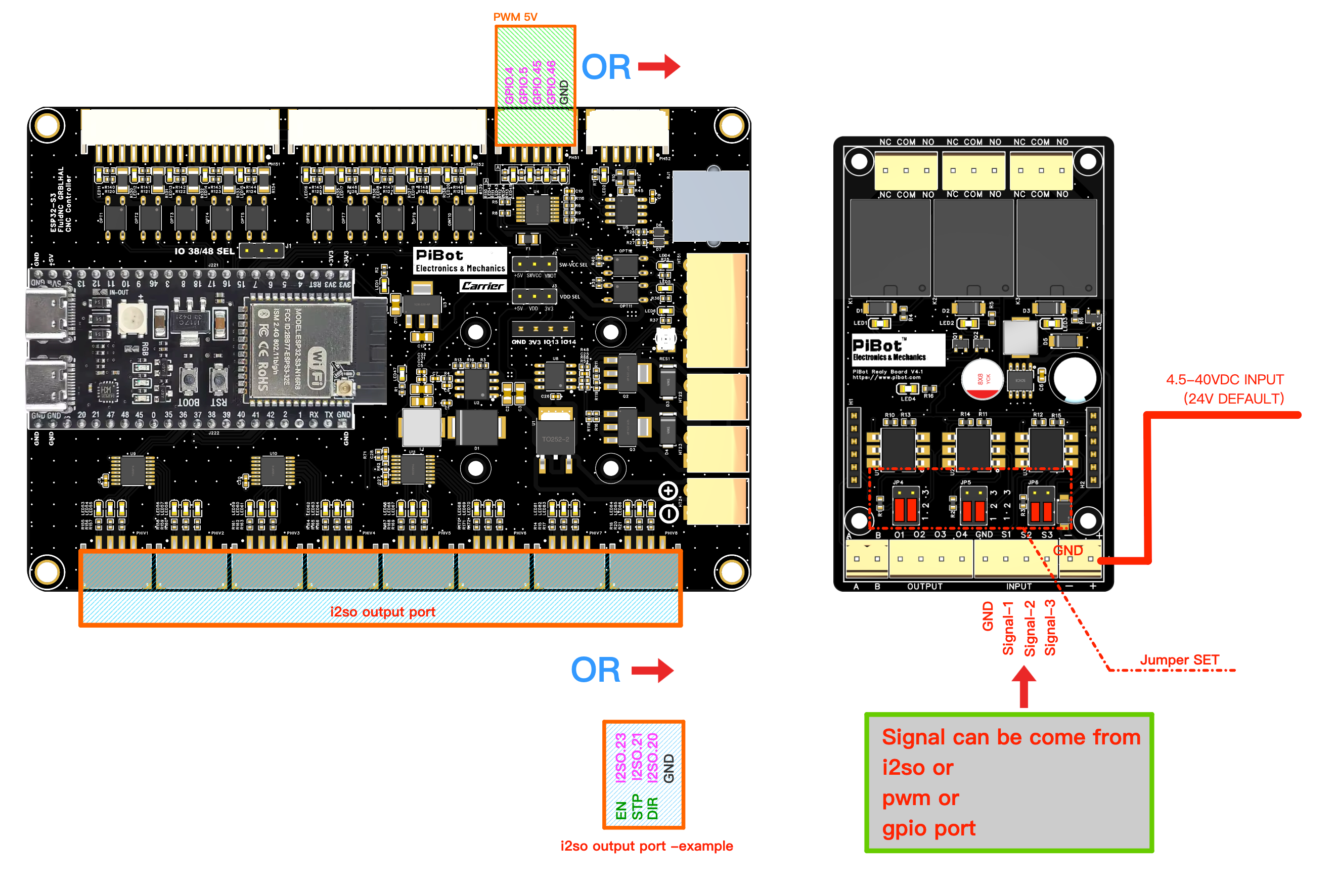
Which outputs you can use on V5.77 Carrier
| Route | Pins | Level | Notes |
|---|---|---|---|
| 5 V buffered output header (labelled PWM 5V) | GPIO.4 GPIO.5 GPIO.45 GPIO.46 + GND | 5 V signal | GPIO.4/GPIO.5 also drive the MOSFET channels; GPIO.45/GPIO.46 are spindle and laser PWM in the test YAML. This header is not a relay-coil supply. |
| I2SO output | I2SO.23 I2SO.21 I2SO.20 + GND | 5 V signal | The C-axis PH2.0 connector in the worked example; use it only when that axis is unused. Extra-I/O I2SO signals may also be assigned, but then they are unavailable to the optional 7th/8th axes. |
Trigger jumpers on the relay board
Each relay has its own jumper block — JP4→S1, JP5→S2, JP6→S3. The silkscreen numbers the rows 1 (bottom), 2 (middle), 3 (top); each column takes one jumper, down bridging 1–2 and up bridging 2–3.
| Setting | Left column | Right column | Effect |
|---|---|---|---|
| Active High — default | down (1–2) | down (1–2) | A high signal energises the relay. |
| Active Low | up (2–3) | up (2–3) | A low signal energises the relay. |
| Always on | up (2–3) | down (1–2) | Stays energised, input ignored. |
| Always off | down (1–2) | up (2–3) | Stays de-energised, input ignored. |
Wire and prove the control side first
- Disconnect the V5.77 and relay-board supplies.
- Choose one route from the table; do not combine routes.
- Wire three signals and GND to S1/S2/S3/GND, then power the relay board from its own supply.
- Set JP4/JP5/JP6 and load the YAML mapping below.
- With no load attached, send one command at a time and check the click and LED.
- Measure COM–NO and COM–NC continuity before connecting the real load.
YAML and test commands
Matching the drawing, where I2SO.23→S1, I2SO.21→S2 and I2SO.20→S3. Substitute your own pins if you wired a different output.
coolant:
  mist_pin: I2SO.23        # S1 - M7 on, M9 off
  flood_pin: I2SO.21       # S2 - M8 on, M9 off
  delay_ms: 0

user_outputs:
  digital0_pin: I2SO.20    # S3 - M64 P0 on, M65 P0 off
Pass: each command changes only its assigned relay and the continuity reading agrees with the selected contact. Fail: a relay starts unsafe, more than one changes, or a command does not release it — disconnect both supplies and correct the YAML, jumpers or contact wiring before adding a load.
Alternative: Drive a 12–24 V DC Relay Coil Directly
- Choose a relay coil whose voltage matches VIN Main.
- Connect coil positive to Vmot-Main and coil negative to io.4-MOS-GND or io.5-MOS-GND.
- The onboard flyback diode protects a correctly polarized inductive load. Verify polarity before power-on.
- In the test YAML, use
M7for GPIO.4,M8for GPIO.5, andM9to turn both off.
Logic-level Relay / SSR Interface
You may instead use GPIO.4/GPIO.5 on the PWM 5 V header or one of the six reserved I2SO outputs. The interface input must accept the selected 3.3/5 V level and must not overload the logic pin. An optically isolated PiBot IsoSwitch or equivalent interface is recommended where electrical isolation is needed.
GPIO.4 and GPIO.5 feed both their header pins and their onboard MOSFET channels, so these are not independent functions.