2.9 Test PWM Output
Check List · Step 9 of 12 · Measure GPIO.4 at 0% / 50% / 100%
🎯 Objective
Test the GPIO.4 PWM output on the PWM 5V header. Set three output levels and confirm the multimeter reading and GPIO.4 indicator follow the command. A multimeter is all you need; no oscilloscope is required.
Disconnect the spindle and laser hardware. Measure only between GPIO.4 and the adjacent GND. GPIO.4 also controls the matching MOSFET output, so do not attach a load during this test.
🔌 How it works: GPIO.4 switches between 0 V and 5 V at 5 kHz. A DC multimeter displays the average: 100% duty is about 5 V, 50% duty about 2.5 V, and off is 0 V.
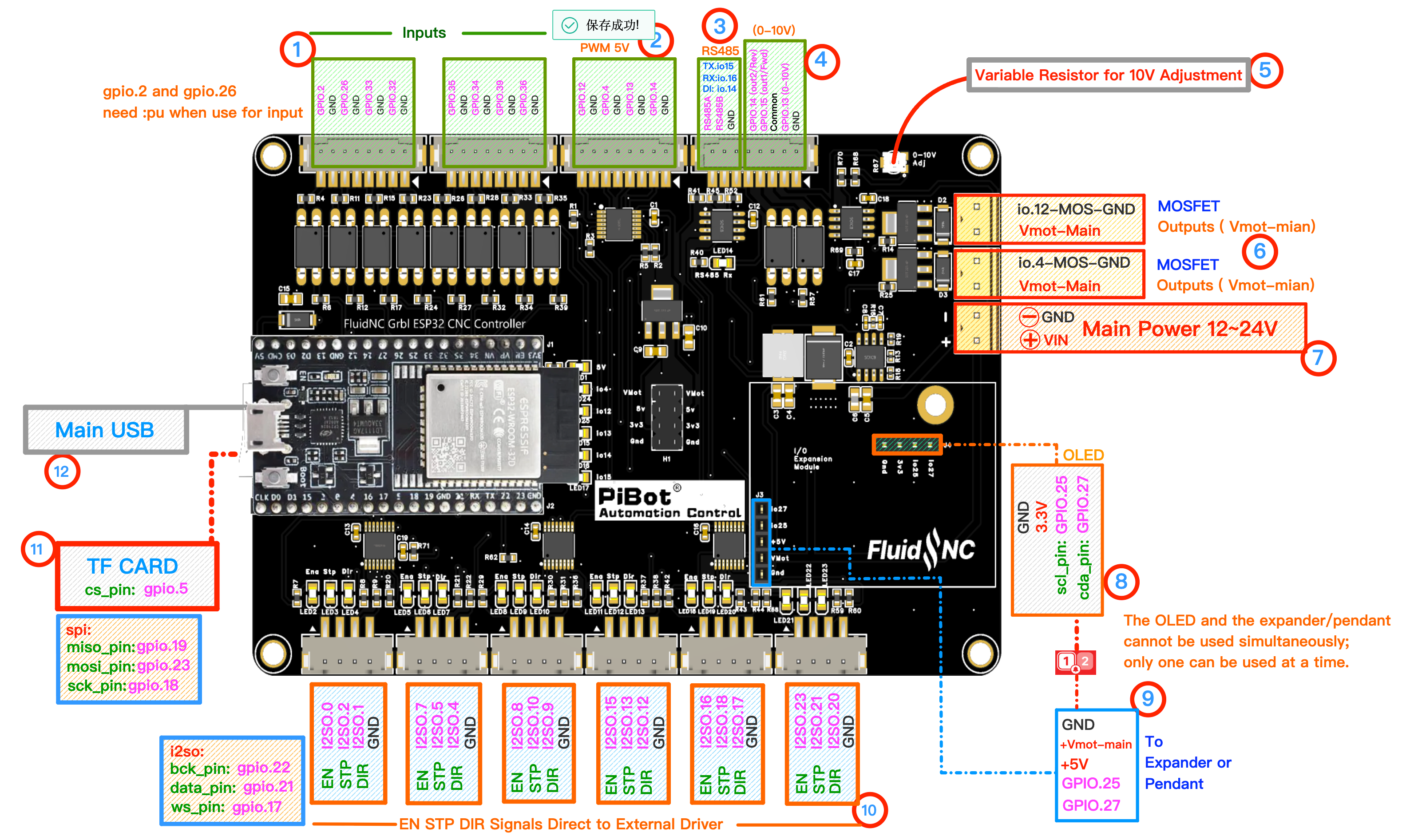
Use numbered area ② PWM 5V: put the red probe on GPIO.4 and the black probe on the adjacent GND. Click to enlarge.
🔧 How to Measure
Set the multimeter to DC voltage, auto-range.
RED (+) → GPIO.4BLACK (−) → adjacent GND
Red on the GPIO.4 pin and black on the GND beside GPIO.4. At half duty the meter reads about 2.5 V.
Send each command in order and wait for the meter to settle.
M6 T0→Select PWM output (tool 0)
M3 S10000→5.0 VGPIO.4 indicator full bright
M3 S5000→2.5 VGPIO.4 indicator half bright
M5→0.0 VGPIO.4 indicator off
✅ Pass: the reading is about 5 V at
S10000, 2.5 V at S5000, and 0 V after M5; the GPIO.4 indicator changes with it.📈 Optional — what GPIO.4 looks like on an oscilloscope. You do not need an oscilloscope for this test.