2.2 Install Module and Power On
Check List · Step 2 of 12 · Install the classic ESP32 module, connect main power, and check startup safely
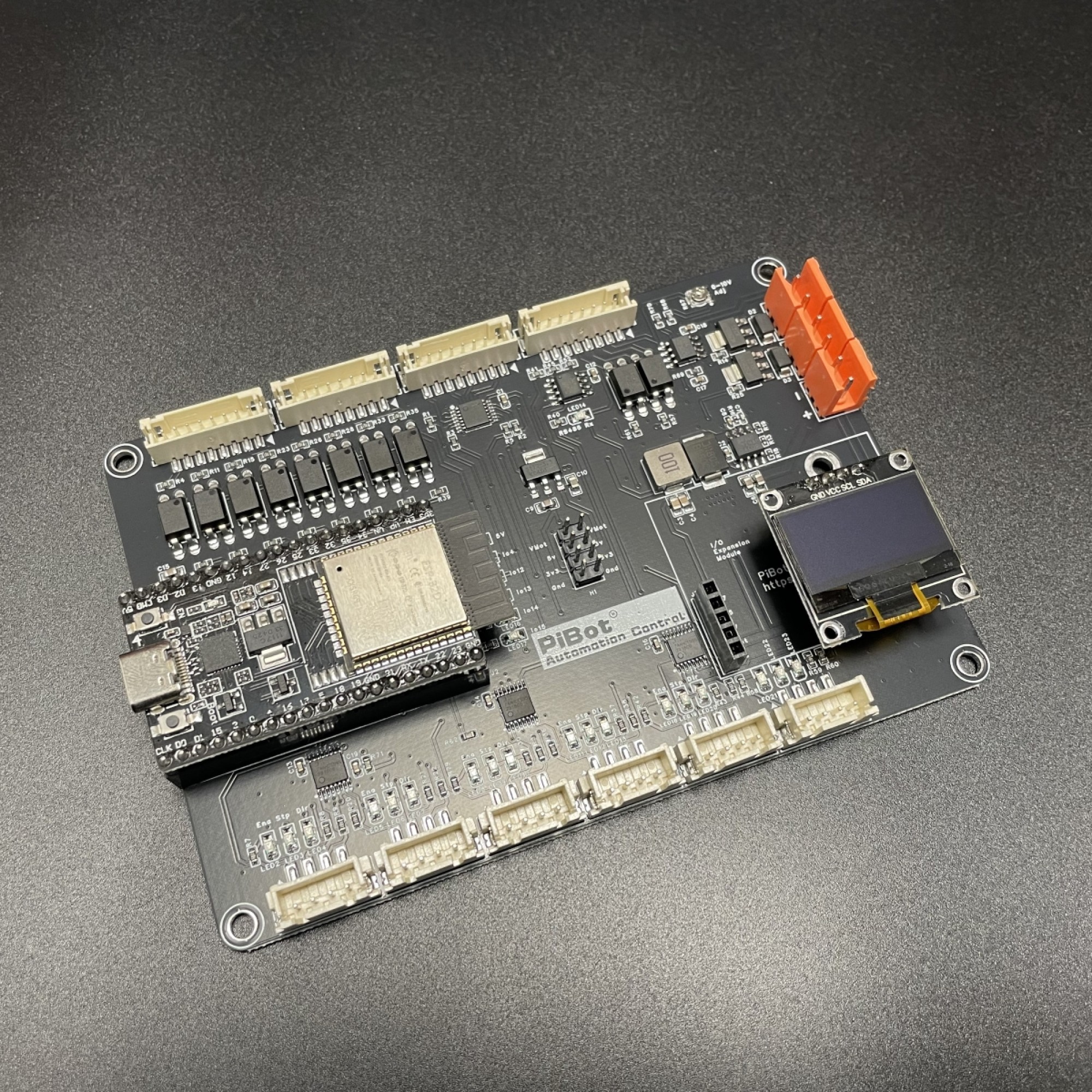
Use this photo and the board silkscreen to match the USB and antenna ends before pressing the module into the two socket rows.
⚠️
SAFETY FIRST: disconnect USB and main power before inserting or removing the ESP32. Leave motors, external drivers, spindle, laser, RJ12 accessories and RS485 wiring disconnected.
🎯 Objective
Seat the correct 38-pin classic ESP32 module without bending or offsetting any pins, then apply correctly polarized 12–24 V power and confirm normal startup.
1
Inspect the Module and Sockets
💡 V4.7B uses a classic ESP32 DevKitC / ESP32-WROOM-32 layout, not the ESP32-S3 module used by V5.77.
- Put the board on a clean, non-conductive surface.
- Confirm both 19-pin socket rows are clean and undamaged.
- Inspect every module pin for bends or contamination.
- Compare the USB connector and antenna end with the product photo and board silkscreen.
2
Install the ESP32 Module
- Align all 38 pins over the sockets before applying pressure.
- Check both long edges from the side. No pin may sit outside or one position away from its socket.
- Press both sides evenly until the module is fully seated.
- Never force the module. Stop and realign it if resistance is uneven.
3
Connect Main Power and USB
- Measure the supply first: it must be between 12 V and 24 V DC.
- Connect positive to VIN / Vmot-main and negative to GND.
- Check polarity again, then switch on main power.
- Connect the module’s micro-USB data cable.
- Stop immediately if there is heat, odor, smoke or abnormal current.
✓
Expected Results
- The module is straight, fully seated and has no exposed or offset pins.
- The carrier-board power indicator and ESP32 indicators operate normally.
- The ESP32 appears as a USB serial device when the data cable is connected.
- There is no abnormal heating, smell or current draw.
Why main power is required
USB can make the ESP32 appear alive while the carrier’s 5 V supply, I2S buffers, input circuits and output indicators remain unpowered. Keep 12–24 V main power connected for the following I/O tests.